


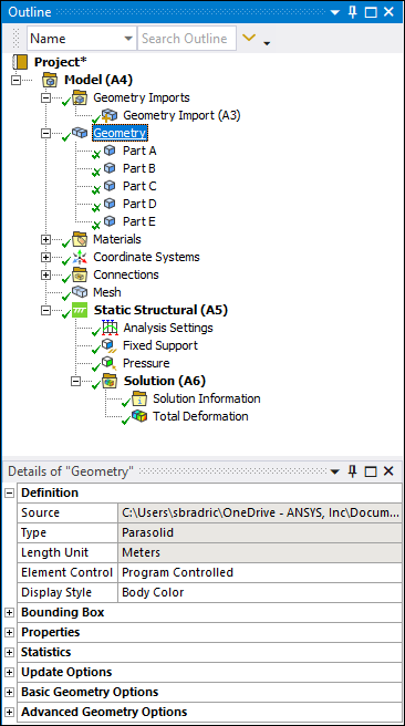
Contains the imported geometry in the form of an assembly or multibody part (objects) from a CAD system or from SpaceClaim/DesignModeler. Assembly parameters, if available, are viewable under the Geometry object. When you select a child object of the Geometry folder, the part (multi-body or otherwise) or body highlights in a unique color. You can change the default color setting using the Graphics preference Geometry Highlight Color in the Options dialog.
The Geometry Context Tab provides the options Attach Geometry and Replace Geometry. The Attach Geometry option is available when you open an analysis system without a geometry. Once you import a geometry into the application, the option is replaced with Replace Geometry. These selections provide a drop-down menu with the options and (available when once you have used the option) to select the newly desired geometry.
 |
Object Properties
The Details Pane for this object includes the following properties.
| Category | Properties/Options/Descriptions |
|---|---|
|
Definition |
Source: Read-only indication of the path and file name associated with the geometry. Type: Read-only indication of how the original geometry was created (CAD product name or DesignModeler). Length Unit: Displays the length unit assigned to the geometry. For most imported geometries, the field is read-only because the unit is defined by the CAD system during import. An exception includes ACIS geometries when length units are not specified. For ACIS geometries without specified length units, the application sets the length unit to the display units and enables you to change the units from the given drop-down menu. Element Control: Allows manual control of the underlying Mechanical APDL element options (KEYOPTS) for individual Part or Body objects beneath the Geometry object. To manually set Mechanical APDL element options, set Element Control to Manual, then select the Part or Body object. Any element options that are available for you to manually set appear in the Details view of the Part or Body object. For example, the Brick Integration Scheme setting for a Part or Body object becomes available only when Element Control is set to . When Element Control is set to , all element options are automatically controlled and no settings are displayed. The Mechanical APDL application equivalent to this setting is the inclusion of the ETCON,SET command in the input file, which automatically resets options for current-technology elements to optimal settings. Refer to the Element Reference for more information about Mechanical APDL elements and element options. Display Style: The default is Body Color which assigns unique colors to individual bodies in a part. Other choices include Body Type, Part Color, Assembly Color (Model assembly only), Shell Thickness (surface bodies only), Material, Nonlinear Material Effects, Stiffness Behavior, and (line bodies only). 2D Behavior: Appears only for a designated 2D simulation. |
|
Length X Length Y Length Z | |
|
Properties |
Volume: Read-only property. Mass: Read-only property. Appears only in the Mechanical application.
Note:
Surface Area (approx.): Read-only property. Displays the approximate surface area of the geometry. This value changes when parts or bodies are suppressed. Scale Factor Value: The value applied to imported geometry for the purpose of modifying the size of the model. The scale factor value of newly imported geometry is 1.0. You can modify this value. Values changes are expected to be preserved on updated models. Due to tolerances, models that are scaled (especially larger) sometimes have problems meshing. The scale factor limit is from 1e-3 to 1e3. Factors entered beyond that range are ignored. Note:
2D Tolerance: For surface bodies (only), this property validates that the geometry is two-dimensional (2D) by checking the value of the Length Z property, using CAD units, in the Bounding Box category (shown above). The default value is 1.e-005. If the application detects a value greater than the Length Z, the Dimension property becomes underdefined. |
|
Statistics: Read-only indication of the entities that comprise the geometry. Active Bodies are those that are unsuppressed compared to the total number of Bodies. |
Bodies Active Bodies Nodes Elements Mesh Metric |
|
Update Options |
Assign Default Material: Controls the preference for default material assignment when geometry is updated in Mechanical. When you first import your geometry into Mechanical, any bodies that do not have a material assigned to it are assigned the application's default material. If you subsequently update your geometry from the source application, and this property is set to (default), Mechanical does not assign the default material to new bodies. If the geometry update includes a new body without an assigned material, the body becomes underdefined and requires you to specify a material. Property options include (default) and . Setting this property to instructs the application to always assign a default material upon update. You can change the default setting of the property by changing the setting of the Assign Default Material to New Bodies Based on Update option of the Geometry category of the Options preference. |
|
Basic Geometry Options |
Solid Bodies Surface Bodies Line Bodies Parameters Parameter Key Attributes Named Selections Material Properties |
|
Advanced Geometry Options |
Use Associativity Coordinate Systems Reader Mode Saves Updated File Use Instances Smart CAD Update Compare Parts on Update Attach File Via Temp File Temporary Directory Analysis Type Mixed Import Resolution Decompose Disjoint Geometry Enclosure and Symmetry Processing |
Tree Dependencies
Valid Parent Tree Object: Model.
Valid Child Tree Objects: Comment, Distributed Mass, Element Orientation, Figure, Image, Layered Section, Part, Point Mass, Surface Coating, Thickness, Imported Element Orientation, and Imported Thickness.
Insertion Methods
Displays automatically when you open a geometry in Mechanical.
Right-click Options
In addition to common right-click options, relevant right-click options for this object include:
>
Thickness (Surface Body only)
Layered Section (Surface Body only)
: Restores the hierarchy structure imported from a CAD file when you change the grouping of the imported structure.
Export - options include:
: Exports the CAD geometry to a binary Part Manager Database (.pmdb) file. You may your entire geometry, individual parts, and/or multiple parts. This option does not support export at the body level of the geometry - only the part that includes the body. This export option facilitates future geometry import into SpaceClaim, DesignModeler, as well as re-importing the file back into Mechanical.
: Export result data as a Ansys Viewer File (.avz).
: Exports object information in Standard Tessellation Language (STL) file format (ASCII only). This option is only available when the Export Format property of the Export preferences is set to .
or > // (option availability based on body type).
API Reference
See the Geometry section of the ACT API Reference Guide for specific scripting information.
Additional Related Information
See the following sections for more information: