Mechanical enables you to organize and group certain objects in the Outline pane. Using context menu (right-click) options, the application provides a number of different options that you use to group objects.
Go to a section topic:
Note: For CAD files with a hierarchy structure, the Options dialog preference setting, Assembly Hierarchy, enables you to automatically group parts and bodies under the Geometry object upon import. If you use this preference, you cannot change the setting once you have imported your geometry. This is due to a geometry update limitation.
Group Multiple Objects
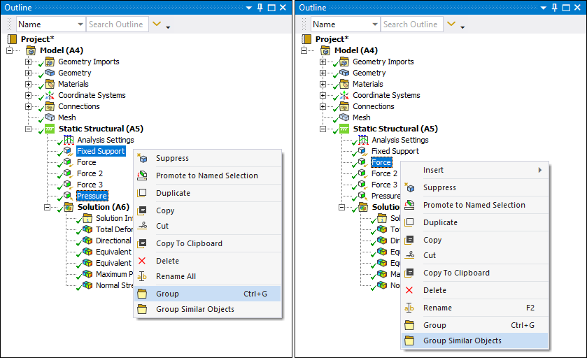
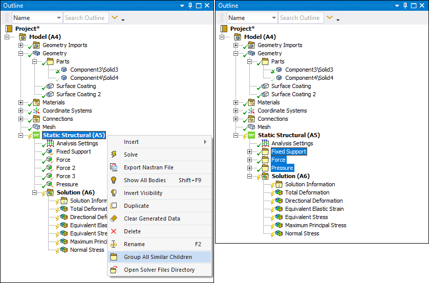
Use the option when you individually select multiple objects to be grouped. The groups together objects of the same type (for example, Pressure, Displacement, etc.) and renames the group folder according to that type.
Note: If you change and update your geometry, always verify your groupings. For example, using the Explode Part feature in DesignModeler alters Part IDs.
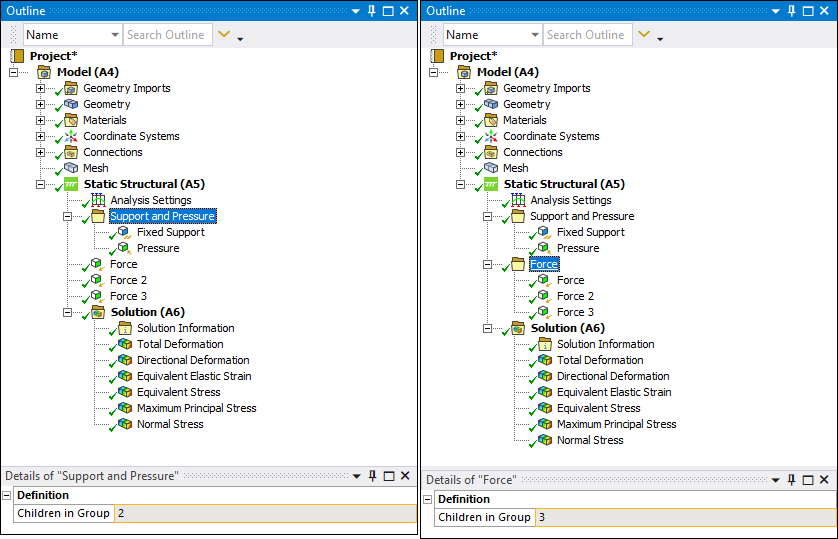
Once you create groups, you are prompted to rename the folder or you may accept the default name (New Folder). In the following example, the folder was named "Support and Pressure." The similar objects folder name is automatically created based on the object type, in this case, Force. Also note that this new object provides the Details view property Children in Group that displays the total number of objects contained in the new group.
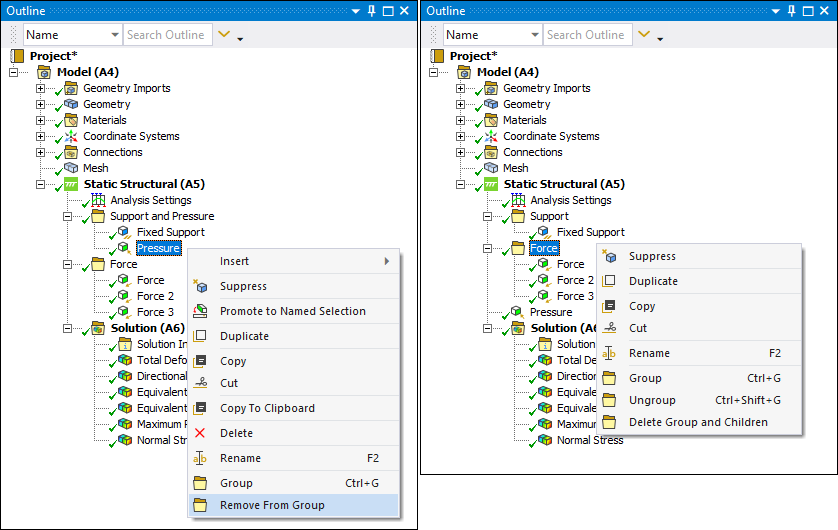
Once defined, options become available that enable you to (and ) a group as well as remove objects from a group (), further group objects into sub-folders/groups (), a particular folder, as well as delete a folder and its sub-folders ( option or [Delete] key). You can also , , and the content of a group folder. And in addition to the context menu options, you can drag-and-drop objects between folders.
Group, Hide, and Suppress Geometry Objects
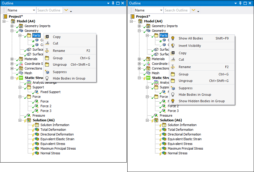
As illustrated below, the Geometry object offers additional grouping options that enable you to Hide and Show bodies inside and outside of a group as well as Suppress/Unsuppress bodies. The F9 hotkey also enables you to hide selected bodies.
Group All
The Mesh, Named Selection, Environment, and Solution objects provide an option to . This option groups together the same type (for example, Mesh Method, Pressure, Stress result, etc.) of objects (that are not already included in a grouping) and automatically names the folder based on that type.
Group Loads by Load Vector (Substructure Generation Analysis Only)
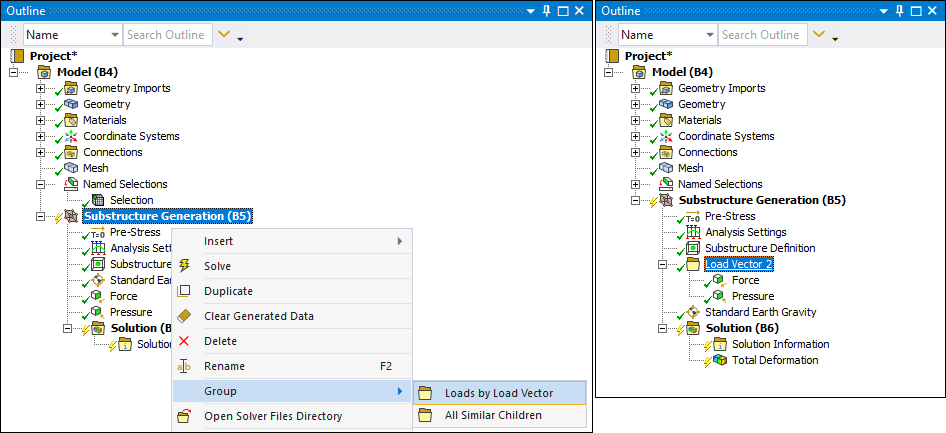
For the boundary conditions supported by the Substructure Generation analysis, the Environment object provides the grouping option: . This option automatically groups environment load objects with the same Load Vector Number, as specified by the Load Vector Controls properties available from the boundary condition object. The application generates a folder based on the corresponding Load Vector Number, as illustrated below for load vector number 2. Note that loads with the same load vector number, that are already included in a group, are not added to the new group.
Objects with Limited Grouping
The following objects have limitations regarding grouping. This includes several objects that cannot be grouped.
Model object children (except Chart) cannot be grouped. However, the child objects of these model-level children may be grouped.
System generated Named Selections under the Fracture object cannot be grouped.
Gasket Mesh Control objects under a Part object cannot be grouped.
Global Coordinate System: this is the application defined Coordinate System and does not support grouping.
Reference Coordinate Systems: These coordinate systems are not defined by the Coordinate Systems object and do not support grouping.
Analysis Settings: grouping not supported.
Initial Conditions (including child objects): grouping not supported.
Solution Information: grouping not supported.


