


After attaching geometry, you can access settings related to part behavior by right-clicking on the Model cell in the analysis system schematic and choosing . The Mechanical application opens with the environment representing the analysis system displayed under the Model object in the tree.
An Analysis Settings object is added to the tree. See the Establish Analysis Settings overall step for details.
An Initial Condition object may also be added. See the Define Initial Conditions overall step for details.
The Mechanical application uses the specific analysis system as a basis for filtering or making available only components such as loads, supports and results that are compatible with the analysis. For example, a Static Structural analysis type will allow only structural loads and results to be available.
Presented below are various options provided in the Details view for parts and bodies following import.
Stiffness Behavior
In addition to making changes to the material properties of a part, you may designate a part's Stiffness Behavior as being flexible, rigid, as a gasket, and can specify a line body as a stiff beam, essentially making the body rigid.
Setting a part's behavior as rigid essentially reduces the representation of the part to a single point mass thus significantly reducing the solution time.
A rigid part will need only data about the density of the material to calculate mass characteristics. Note that if density is temperature dependent, density will be evaluated at the reference temperature. For contact conditions, specify Young's modulus.
Flexible and rigid behaviors are applicable only to static structural, transient structural, rigid dynamics, explicit dynamics, and modal analyses.
Gaskets can be defined in one of two ways:
By setting the Stiffness Behavior as Gasket. In this case, a Gasket Mesh Control will be added as a child of the gasket body in the model tree. You need to define the source face of the gasket in the Gasket Mesh Control to define the gasket material orientation.
By setting the Stiffness Behavior as Flexible. In this case, you need to define a Gasket Mesh Control in the mesh folder. The gasket mesh control in the mesh folder can be applied to multiple bodies, so if there are many gasket bodies this option may be a more convenient approach to setting up the gaskets.
Gasket Bodies are only applicable to static structural analyses. The Material Assignment of gasket bodies should reference an appropriate gasket material.
is the default Stiffness Behavior. To change, simply select , , or (for a line body only) from the Stiffness Behavior drop-down menu. Also see the Rigid Bodies, Gasket Bodies, and/or Stiff Beam sections.
Note: behavior is not available for the Samcef or ABAQUS solver.
Coordinate Systems
The Coordinate Systems object and its child object, Global Coordinate System, is automatically placed in the tree with a default location of 0, 0, 0, when a model is imported.
For solid parts and bodies: by default, a part and any associated bodies use the Global Coordinate System. If desired, you can apply a apply a local coordinate system to the part or body. When a local coordinate system is assigned to a Part, by default, the bodies also assume this coordinate system but you may modify the system on the bodies individually as desired.
For surface bodies, solid shell bodies, and line bodies: by default, these types of geometries generate coordinates systems on a per element type basis. It is necessary for you to create a local coordinate system and associated it with the parts and/or bodies using the Coordinate System setting in the Details view for the part/body if you wish to orient those elements in a specific direction.
Reference Temperature
The default reference temperature is taken from the environment (By Environment), which occurs when solving. This necessarily means that the reference temperature can change for different solutions. The reference temperature can also be specified for a body and will be constant for each solution (By Body). Selecting By Body will cause the Reference Temperature Value field to specify the reference temperature for the body. It is important to recognize that any value set By Body will only set the reference temperature of the body and not actually cause the body to exist at that temperature (unlike the Environment Temperature entry on an environment object, which does set the body's temperature).
Note: Selecting By Environment can cause the body to exist at that temperature during the analysis but selecting By Body will only ever effect reference temperature. So if the environment temperature and the body have a different specification, thermal expansion effects can occur even if no other thermal loads are applied.
Note: If the material density is temperature dependent, the mass that is displayed in the Details view will either be computed at the body temperature, or at 22°C. Therefore, the mass computed during solution can be different from the value shown, if the Reference Temperature is the Environment.
Note: When nonlinear material effects are turned off, values for thermal conductivity, specific heat, and thermal expansion are retrieved at the reference temperature of the body. These values are available after creating the Mechanical APDL solver input.
Reference Frame
The Reference Frame determines the analysis treatment perspective of the body for an Explicit Dynamics analysis. The Reference Frame property is available for solid bodies when an Explicit Dynamics system is part of the solution. The valid values are (default) and . Eulerian is not a valid selection if Stiffness Behavior is set to .
Material Assignment
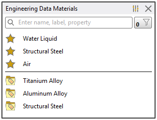
Once you have attached your geometry, you can change the material assigned to the parts and bodies of your model. When you select a Part or Body object in the Outline, there is an Assignment property available in the Details view for each. This property provides a selectable fly-out menu that opens that opens the following Engineering Data Materials window. By default, this window lists the materials included in the Engineering Data favorites, as symbolized with the star icon as well as any other materials that you made available from the Engineering Data workspace, such as titanium and aluminum alloy show below. Selecting a material from this window assigns it to the currently selected part or body.
When you edit the currently assigned material, create a material, or import a material, you work in the Material Data tab. Once you have completed any of those operations, you must refresh the Model cell in the Project Schematic to bring new data into Mechanical.
Note:
The Assignment property can be designated as a parameter.
To model a gasket, the material assignment should reference a valid Gasket Material Model.
Nonlinear Material Effects
You can also choose to ignore any nonlinear effects from the material properties.
By default the program will use all applicable material properties including nonlinear properties such as stress-strain curve data.
Setting Nonlinear Effects to will ignore any nonlinear properties only for that part.
This option will allow you to assign the same material to two different parts but treat one of the parts as linear.
This option is applicable only for static structural, transient structural, steady state thermal and transient thermal analyses.
Thermal Strain Effects
For structural analyses, you can choose to have Workbench calculate a Thermal Strain result by setting Thermal Strain Effects to . Choosing this option enables the coefficient of thermal expansion to be sent to the solver.
Cross Section
When a line body is imported into the Mechanical application, the Details view displays the Cross Section field and associated cross section data. These read-only fields display the name and data assigned to the geometry in DesignModeler or the supported CAD system, if one was defined. See Line Bodies for further information.
Model Dimensions
When you attach your geometry or model, the model dimensions display in the Details Pane in the Bounding Box sections of the Geometry or Part objects. Dimensions have the following characteristics:
Units are created in your CAD system.
ACIS model units, if available during import and/or update, are used.
Other geometry units are automatically detected and set.
Assemblies must have all parts dimensioned in the same units.