


Generates a support structure consisting of finite elements for Additive Manufacturing simulations. Elements are generated between the part geometry and the base plate geometry based on an existing mesh and the criteria set in Support Group.
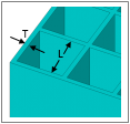
After inserting this object, select element faces of the part under which you want elements to be generated. Then right-click and select Generate Support Bodies to generate the elements. Elements are generated straight down from there to fill the gap between the part and the base plate.
 |
Object Properties
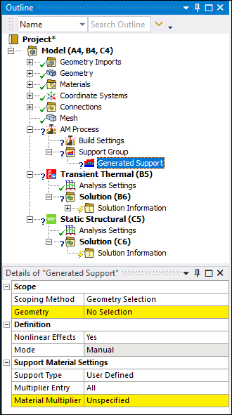
The Details Pane properties for this object include the following.
|
Category |
Properties/Options/Descriptions |
|---|---|
|
Scope |
Scoping Method: Options include (default) and . Geometry: Displays when the Scoping Method is set to Geometry Selection. Using the Element Face selection filter on the graphics toolbar, select the desired element faces and click . Named Selection: Displays when the Scoping Method is set to Named Selection. It provides a drop-down menu. Only element face-based Named Selections are displayed in the drop-down menu. |
|
Definition |
Nonlinear Material Effects: Options include (default) and . This property applies nonlinear material effects to the finite element body. Mode: Indicates whether you manually specified the Geometry Selection or whether it was detected using the options of the Support Group object. Important: Only automatically generated supports are affected by the Generate on Remesh property of the Support Group object
Visible: Show or hide the generated finite element body wherever the mesh is displayed (using the Show Mesh option or when the mesh object is selected). |
|
Support Material Settings |
Support Type: Options include (default) and . When you select the option, the following properties become the only visible properties.
Multiplier Entry: Options include (default) and . Material Multiplier
|
|
Statistics |
Nodes: Read-only property that displays the nodes of the added finite-element body. Elements: Read-only property that displays the elements of the added finite-element body. Volume: Read-only property that displays the volume of the added finite-element body. |
Tree Dependencies
Valid Parent Tree Object: Support Group, which is under AM Process object.
Valid Child Tree Objects: None.
Insertion Methods
Select the AM Process object and then select the Generated Support option from the AM Process Context Tab.
Right-click the AM Process object and then select the > .
Select the Support Group object and then select the Generated Support option from the AM Process Context Tab.
Right-click the Support Group object and then select the > .
Right-click Options
In addition to common right-click options, relevant right-click options for this object include:
API Reference
See the Generated AM Support section of the ACT API Reference Guide for specific scripting information.