


The Graphics group includes the following categories and preferences. This group contains a large number of preferences. Go to a desired category using the following links:
| Category | Preference | Description |
|---|---|---|
| Default Graphics Options | Reset Views on Geometry Refresh | Specify whether the application automatically resets the graphical view (display angle) of your model in the Geometry window when you refresh the geometry. Options include (default) and . |
| Max Number of Annotations to Show | A slider that specifies the number of annotations that are shown in the legend of the Geometry window. The range is adjustable from to . The default setting is . | |
| Show Min Annotation | Specify whether the minimum annotation will be displayed by default (for new databases). Options include (default) and . | |
| Show Max Annotation | Specify whether the maximum annotation will be displayed by default (for new databases). Options include (default) and . | |
| Obscured Label Display Style | When you have an annotation label applied on either the Mesh object or on a result object, or you have a probe label applied to a result, this preference lets you choose whether to have the label/probe show “through” the model when it is not visible because of the model’s current orientation. Options include (default), , and . | |
| Unobscured Label Tolerance Factor | There may be times when a label displays as obscured when it should not. This is most often a result of how the application calculates the location of a label. There are instances when a label’s position will be located beneath the surface of a body. For the above or options, this tolerance enables you make small adjustments to the tolerance factor to make sure that the label behaves as expected. The tolerance range is between and . Small incremental changes, such as , can be appropriate to properly display obscured labels. | |
| Number of Local Min/Max Probes | Specify the number of Min/Max probe labels you wish to display for your result data. The default setting is . The supported range is -. | |
| Contour Menu | Selects default setting for the Contours menu (Result
Context tab). Options include:
| |
| Flat Contour Tolerance | Flat contours (no variation in color) display if the minimum and maximum results values are equal. The comparison of the minimum and maximum values is made using scientific notation with the number of significant digits to the right of the decimal point as specified with the flat contour tolerance setting ( to ). Increasing this tolerance enables you to display contours if the range of values is too narrow. Decreasing this tolerance prevents insignificant range variations from being contoured. This setting has a default value of . | |
| Edges Menu | Specify the default setting for the Edges menu options
(Result Context tab). Options include:
| |
| Highlight Selection | Specify the default behavior of the Face selection filter when working with surface bodies. The application automatically selects one or both sides of the surface. Options include (default) and . | |
| Number of Circular Cross Section Divisions | Specify the default number of divisions to be used for viewing line body cross sections for circular and circular tube cross sections. The supported range is from to . The default is 16. | |
| Mesh Visibility | Specify whether to automatically display the model’s mesh when you select the Mesh object or to only manually display the mesh by selecting the Show Mesh button. Options include (default) and . | |
| FE Annotation Color | This option enables you to change the default coloring for FE related annotations (FE-based Named Selections and/or objects scoped to Nodes or Elements). It also changes the color of the elements displayed for an Analysis Ply object. | |
| Mesh Failed Color | Set the default color of the Mesh Failed annotation. | |
| Mesh Obsolete Color | Set the default color of the Mesh Obsolete annotation. | |
| Geometry Highlight Color | Specify the default color used when a part or body is selected from the Geometry folder. | |
| Model Rotation Center | Set the default behavior of the rotation option. Options include:
| |
| Shell Expansion Edge Angle | Set the angle used to determine whether adjacent element normals are averaged. This is applicable when shell thickness is being applied to the mesh to represent the actual thickness. The range is adjustable from to . The default is 180. | |
| Line Body Thickness | Set how line bodies are displayed in the Geometry window. Selections include (default) and . | |
| Mouse Rotation Mode | Set the default behavior of the
cursor for the Rotate option of the Graphics toolbar. Selections include:
Note: The Rotate button offers a drop-down menu to switch between free and axis rotation. This option also defines the default behavior. | |
| Triad Smooth Rotation | Specify that the application computes the shortest path between model positions when using the Triad feature in order to facilitate smoother model rotations. Options include (default) and . | |
| Show Coupled Physics Analysis | For analyses that support the use of the Physics Region object, this preference enables you to display the bodies and/or parts associated with each properly defined Physics Region as a different color when the Environment object is selected. Options include and (default). | |
| Consider Section Planes When Mesh Picking | Activate this preference to select newly displayed finite element entities (nodes, elements, and element faces) from geometries within the model that were hidden prior to adding a Section Plane. Options include and (default). See the Selecting Mesh Entities Displayed by the Section Plane topic for additional information. | |
| Animation Draw Option | By default, the application displays a result animation as it is being processed. In previous releases, the application would first process and then display result animations. You can revert to the previous display method by setting this property to . Options include (default) and . | |
| Use Deformed Edge for Slice ISO Option | This preference applies to the , , and options of the Geometry menu and the and options of the Edges menu, both of the Result Context tab, and how they work together. When you set this preference to , the , , and options display the selected result in a deformed state but a wireframe overlay () of the model or a translucent overlay () of the model in an undeformed state. Options include (default) and . | |
| Hide Unsupported OpenGL Version Warning | Use this preference to display a warning message under the Ansys logo if your computer is using an unsupported version of OpenGL, including any version prior to 4.3. This may help diagnose the availability of certain graphics features in Mechanical. Options include (default) and . | |
| Disable 2D Overlays (Linux Platform Only) | When active, this preference stabilizes the graphical display by preventing your model from disappearing during mouse movements. This option also turns off a variety of display features, such as the ability to highlight geometry selections (single, box select, lasso, etc.) prior to selecting a geometric entity, as well as graphics labels (such as interactive probe labels). These display and selection features operate properly, but do not provide pre-selection highlights and labels. Options include and (default). | |
| Mesh Translucency | This preference defines the translucency of the displayed mesh. The slider option has a range of (no translucency) to (totally transparent). The default setting is . | |
| Maximum Face Angle to Preserve Edges | When you have the Edges result display set to , you could experience display issues for edges
when the tolerance angle between two faces is insufficient. This preference enables
you to increase this tolerance angle. The default setting is
120°. Supported entry range is
0° to 180°. | |
| Use this preference to specify the desired sampling level for the display of the model in the Geometry window. The sampling process smooths the display of jagged edges. Options include , , , and the default . You can cycle through these settings using the key combinations Shift+[1] through Shift+[4]. | ||
| Contour Edge Line Weight | For results scoped to edges, this preference enables you to specify the thickness of edge result contours. It provides an entry field combined with a slider option. The setting range is to . The default setting is . | |
| Color Mesh Edge Using Body Color | This preference enables you to change the color of mesh lines/edges from the default black to the mesh body's color in order to improve edge visibility for dense meshes. Options include and (default). | |
| Interactive and Min/Max Probes | Move Probe Labels with Deformation Scale Factor | Enables probe labels to move with a deformed mesh when you make a change to the Deformation Scale Factor. Options include (default) and . If set to , the application deletes probe labels whenever you change to the scale factor. |
| Show Mesh Entity ID in Snap-Probe Labels | When the Snap option is selected, this preference enables you to automatically display Node or Element IDs on probe annotations. Options include (default) and . | |
| Probe Line Color | Set the color of the line that connects a probe label to its location on the model. | |
| Show Detailed Information in Min/Max Probe Labels | Specify whether to automatically display the min/max values as well as Node or Element IDs on probe annotation labels. Options include and (default). | |
| Probe Tool and Hit Point Coordinate[a] | Font | Arial is the default font. Ten font types are available for selection. |
| Size | The font size is in pixels. 18 is the is the default size. The size range is 10 to 30. | |
| Style | Styles include Regular (default), Bold, Italic, and Bold Italic. | |
| Color | White is the default color. A color palette displays when you select this option. | |
| Lighting[b] | Ambient | Default value is . |
| Diffuse | Default value is . | |
| Specular | Default value is . | |
| Color | White is the default color. | |
| Force White Lighting for Results | When you change the Color property from white, this property enables you to make sure that load variation contours and result contours will correspond to the color contours of the legend. Options include and (default). | |
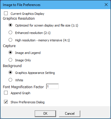
| Image Export | Current Graphics Display | When exporting an image to a file using the option, this preference defines whether or not to copy the image
directly from the viewport without re-rendering the image. Options include
and (default). Setting
this preference to displays the Image to
File Preferences dialog with all of the available options visible. Use
these options to change how the application renders an exported image. Dialog
options are described below.
|
| Graphics Resolution | Set the default resolution setting for exporting images. Options include:
Note: The Ansys logo does not scale at higher resolution settings. | |
| Instructs the application to use the setting of the Graphics Resolution preference (described above) when you use the option of the Images drop-down menu (Home tab/Insert group). Settings for this preference include and (default). | ||
| Capture | Specify whether to include legend content in the image. Options include (default) and . | |
| Background | Set the background coloring. Options include (default) and . The setting is based on the background color setting. | |
| Font Magnification Factor | Set the font size of legend content. The magnification range for the font size
is 0.5 to 1.5. If you enter a value
less than or greater than this range, the application will default to the
corresponding minimum (0.5) or maximum
(1.5) value. The default value is 1.
This setting also scales the contour color band. | |
| Append Viewport Graph | Specify whether to include Graph window data on the captured image. If there is no corresponding data in the graph, the captured image includes a graph with no data. Options include and (default). When set to , the corresponding setting on the Image to File Preferences dialog is automatically selected. | |
| Show Preferences Dialog | This preference determines whether a dialog box automatically displays when you select the Image to File option. The dialog box contains all of the above options. If disabled using this option, the application saves the most recent settings that you have used. Yes (default) or No. | |
| Rescale Graph Overlay | When you choose to include Graph window data on your image, this preference automatically scales the graph content to match the selected resolution. Options include (default) and . | |
| Composite Image Borders | The application automatically adds the borders around/in-between the captured viewports or includes no borders. When you select one of the border options, the corresponding setting(s) on the Image to File Preferences dialog is/are automatically activated. Options include (default), , , and . | |
| Probe Label Offset | The options for this preference relate to how the application captures and
saves images of results displayed in the Geometry window as
well as how the application presents images on the Print Preview tab, when you have inserted Probe labels
and then moved those probe labels on
the screen. Options include:
| |
| Animation Export | Legacy Animation Export | Setting this preference to enables you to export AVI animation files using Microsoft Windows API on the Windows platform. The default setting is . |
| Legend | Orientation | Select a desire display orientation for the legend. Options include (default) and . |
| Show Min/Max on Color Bar | Either display or hide (default) the legend's context menu (right-click) option Show Min/Max on Color Bar. Options include and (default). | |
| Show Deformation Scale Factor | Either display (default) or hide the legend's context menu (right-click) option Show Deformation Scale Factor. Options include (default) and . | |
| Show Date and Time | This preference enables you turn off the display of the date and time in the Geometry window. The context (right-click) menu option Date and Time also changes this default setting. Options include Yes (default) and No. | |
| Max Number of Labels to Shown in Legend | A slider that specifies the number of annotations that are shown in the legend of the Graph window when you are using Charts. The range is adjustable from 0 to 50. The default is 10. | |
| Performance | Accelerated Graphics for Mesh/Result Display | See the Accelerated Graphics
section for more information. Property options include:
|
| Animation Mode | Options include:
| |
| Use Faceted Lighting for Accelerated Graphics/Animation | This preference enables you to modify lighting. Options include and (default). The option specifies the standard lighting mode. This setting can cause issues with large deformation, but maintains smooth lighting and may be suitable for most models. The setting uses an alternate faceted lighting mode. Lighting is on a per-triangle basis, resulting in a more jagged rendering of some models. The lighting should still be correct for any deformation. | |
| Show Why Accelerated Graphics is Not Used | When possible, display an information message for why Accelerated Graphics (or
Accelerated Animation) are not used for the mesh and results. Options include
(default) and . Note: Informational messages may display even when the Accelerated Graphics feature is disabled because this preference also supports Accelerated Animation. Accelerated Animation is controlled by the Animation Mode preference described above. | |
| Edge Connectivity Display Mode | This preference controls an internal algorithm used to compute and highlight
the model edges when the By
Connection option is selected. Options include
(default) and
. Important: When set to , hidden faces are not considered when computing the number of shared edges. | |
| Show Accelerated Display Message in Graphics Window | This preference enables you to turn the “Accelerated Display” label on and off. Options include (default) and . | |
| Accelerated Graphics for Body Load Display | This preference enables the Accelerated Graphics feature to be used for supported imported thicknesses and imported loads. Options include Yes (default) and No. | |
| Level of Detail (Beta) | This preference defines two separate behaviors: 1) the level of complexity for the graphical display of the model in the Geometry window and 2) the speed it to takes select objects in the Outline. See the beta documentation for this option. | |
| Varying Loads (Optimization Options) | Specify how varying loads display in the Geometry window. Options include (default) and . The setting displays variable load contours normally. The option displays colored discrete points on the model, based on legend colors, of the load variation. This option provides significantly faster redrawing times. The computational improvement may be desirable for models with a large number of parts/bodies. |
[a] The category enables you to change the default values for the attributes (font, size, style, color) of the font displayed for the Probe annotations.
[b] The Lighting category enables you to change the default values for the following properties of the Model object. Lighting preferences are project-based, therefore, when you change one of these default settings, you must close Mechanical and Workbench and then begin a new project. Once established, all future saved projects will include the preferences. Any previously saved projects will have the lighting defined when the project was saved.