


The Element Orientation feature is used define the orientations and alignments of elements/bodies for a given model. It enables you to define the coordinate system of one or more manually selected elements or each element of a specified body. As described below, there are two application methods for the Element Orientation feature: either the Surface and Edge Guide option that is the default, or the Coordinate System option. An example of each option accompanies the application steps. In addition, review the procedure used to generate orientations when using the Surface and Edge Guide option as well as the display options that enable you to change the how you wish to view the orientation vectors in the graphics window.
Also see the Element Orientation object reference page for additional information about this feature.
Note: Element Orientations can also be imported through External Data or the External Model system. See the Imported Element Orientation (External Data) and Imported: Element Orientations (External Model) object reference pages for more information.
Requirements
Note the following requirements for this feature:
It is supported for 3D solids and shells.
If multiple edges are selected in the Edge Guide category, the edges must be connected.
The feature is not supported by the Rigid Body or Explicit Dynamics analysis systems.
The LS-DYNA analysis system supports element orientation.
Caution: When solving your analysis, you may receive the following message if you are using the Element Orientation feature and your Ply/Layer data has overlapping elements.
| "Some Element Orientations will be ignored in the solution process due to overlapping elements from Imported Plies." |
Note:
For shell elements, this feature uses the projection of the local system on the shell surface. As a result, the element orientations displayed in the graphics window will be the same as those used by the solver.
If you want to import Element Orientations from an upstream Mechanical system to a downstream Mechanical system, the application only supports Element Orientations defined by a coordinate system.
For specific technical information about this feature, refer to the ESYS command in the Mechanical APDL Command Reference as well as the Understanding the Element Coordinate System in the Mechanical APDL Element Reference.
Application
- Surface and Edge Guide Option (default option)
To define your element orientation using the option:
Select the Geometry object in the tree.
Select the option on the Geometry Context tab or right-click and select > or right-click in the Geometry window and select >. The new object becomes the active object.
Note: You can insert multiple Element Orientation objects into the tree. The last object inserted supersedes previous objects that have the same body scoping.
In the Scope category of the Details view:
Define the Scoping Method as either or .
Select the body you wish to apply orientations to and, click in the Geometry property's field, and then click the button. You can also specify an element or elements as well as a desired geometry- or element-based Named Selection.
Note: The body you select may have an existing coordinate system scoping; however, once defined by an Element Orientation system, the feature overwrites any existing coordinate systems.
In the Definition category of the Details view specify the Defined By property as .
In the Surface Guide category of the Details view:
Define the Scoping Method as either or .
Select the face or faces that you wish to define to be the Surface Guide, click in the Geometry property's field, and then click the button. Or, specify a desired Named Selection. You can select multiple faces to define this surface geometry.
Specify the axis for the perpendicular direction from the Axis property drop-down list, either , , or .
In the Edge Guide category of the Details view:
Define the Scoping Method as either or .
Select the edge or edges that you wish to define as tangent to the target body, click in the Geometry property's field, and then click the button. Or, specify a desired Named Selection.
Specify the axis for the tangent direction from the Axis property drop-down list, either , , or .
Right-click the Element Orientation object and select .
Note: This feature requires an X, Y, and Z coordinate. You define two of the coordinates, surface and edge, and the application calculates the third required coordinate.
Select the Wireframe view option to view the new orientations.
Surface and Edge Guide Orientation Example
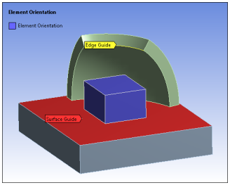
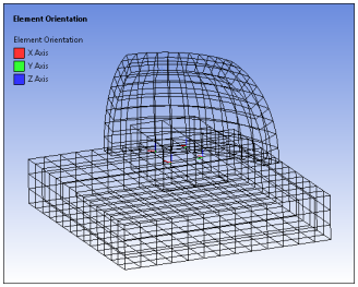
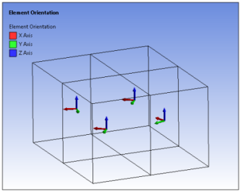
The following images illustrate the use of the option. The first image shows the defined body (in purple) and the Surface Guide (red face) and Edge Guide (yellow edge) selections. The second image illustrates the internal element orientations that were generated with all bodies displayed and the third image is an enlargement of the target body only.
|
|
|
|
- Coordinate System Option
To define your element orientation using the option:
Select the Geometry object in the tree.
Select the option on the Geometry Context tab or right-click and select > or right-click in the graphics window and select >. The new object becomes the active object.
Note: You can insert multiple Element Orientation objects into the tree. The last object inserted supersedes previous objects that have the same body scoping.
In the Scope category of the Details view:
Define the Scoping Method as either or .
Select the body you wish to apply orientations to and, click in the Geometry property's field, and then click the button. You can also specify an element or elements as well as a desired geometry- or element-basedNamed Selection.
Note: The body you select may have an existing coordinate system scoping; however, once defined by an Element Orientation system, the feature overwrites any existing coordinate systems.
Note: The body you select may have an existing coordinate system scoping; however, once defined by an Element Orientation system, the feature overwrites any existing coordinate systems.
In the Definition category of the Details view specify the Defined By property as .
Set the Coordinate System property to the desired coordinate system that you have created. One single triad automatically displays on the applicable region. No other triads are shown, unlike the option.
Select the Wireframe view option to view the new orientations.
Coordinate System Orientation Example
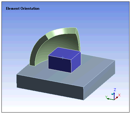
The following images illustrate the use of the option. The first image shows the defined body and the second image illustrates the coordinate-based element orientation.
|
|

|
Generation Procedures for Surface and Edge Guide Option
The Surface Guides and Edge Guides use the following procedure to generate orientations:
Identify one or more surfaces to be the surface guide and one or more edges to be the edge guide.
Identify the 1st axis (for example, z-axis) that will align normal to the surface guide.
Identify the 2nd axis (for example, x-axis) that will align itself tangential to the edge guide.
For each element in the selected body:
The application obtains the surface normal direction (N-vector) at a location on the Surface Guide closest to the element's centroid and aligns the specified axis (z-axis) with it.
The application obtains the tangential direction (T-vector) to the edge at a location on the Edge Guide that is closest to the element's centroid.
The cross-product of the N-vector and T-vector calculate the 3rd axis (y-axis).
The tangential, 2nd axis (x-axis), is obtained by taking the cross-product of the N-vector and the 3rd axis.
Display Options
Once orientations are generated, the Vector Display group appears in the Geometry Context tab.
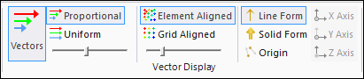
Note: Because Element Orientations have no magnitude, vector length is always uniform and therefore, the Proportional and Uniform options are inactive.
The Display options provide the following features.
| Option | Illustration | Description |
|---|---|---|
|
Vectors |

|
Selecting this option activates the associated display options. |
| Element Aligned |

| Displays all vectors, aligned with each element. |
| Grid Aligned |

| Displays vectors, aligned on a uniform grid. |
| Density Slider |

| Controls the relative size of the grid, which determines the quantity (density) of the vectors. Increases are made in uniform steps from 0 [coarse] to 100 [fine] (default = 20), as displayed in the tool tip when you drag the mouse cursor on the slider handle. This control is only available when the Grid Aligned option is selected. |
|
Scaling Slider |
|
Controls the relative length of the vectors in incremental steps from 1 to 10 (default = 5), as displayed in the tool tip when you drag the mouse cursor on the slider handle. |
| Line Form |

| Displays element vectors as line arrows. |
| Solid Form |

| Displays element vectors as solid arrows. |
|
Origin |

|
Displays origin of the nodes included in each element orientation. |
| X Axis |

| Turns the display of the X Axis of an element on and off. |
| Y Axis |

| Turns the display of the Y Axis of an element on and off. |
| Z Axis |

| Turns the display of the Z Axis of an element on and off. |
These options are similar to the options of the Vector Display for results.