The Pull feature enables you to extrude and revolve element faces, geometric faces, or scoped (surface only) bodies from a surface or a solid mesh. The feature also enables you to create a surface coating on solid bodies, the faces of 3D bodies, element faces (requires mesh), and the edges of 2D axisymmetric surface bodies.
Jump to a section topic using the following links:
Overview
The menu for the feature is displayed when you use the context (right-click) menu of the Mesh or Mesh Edit objects or using the drop-down menu on the Mesh Context Tab. Pull menu options include:
: Create specified layers of solid elements based on height input. Supported scoping includes body (surfaces only), faces, or element faces.
: Create solid element based on angle of revolution. Supported scoping includes body (surfaces only), faces, or element faces.
Note: For the and options, you can automatically apply your extrusion or revolution to Named Selections scoped to the Pull body using the Associate To Pull Geometry property of the Mesh Edit object. See the next section, Associating Named Selections To Pull Geometries, for the steps to use this feature.
:
- 3D Body
For a three-dimensional body, you use this option to create a coating of shell elements on top of a face of an existing body. This can include a body created by the Extrude and Revolve options. The mesh of the new surface body matches the underlying solid body. You can then use this body in an analysis as you would any body. For example, you could scope a result to it.
- 2D Surface Body
You can scope the Surface Coating option of the Pull object to the edges of a two-dimensional axisymmetric surface body to create a line body from the underlying mesh. You can use the generated line body to study the influence of coatings (such as paint) on these axisymmetric structures. These line coatings are represented by the elements SHELL208 (lower order) and SHELL209 (higher order). For the surface body (under Geometry object) that you scope to, the following property settings are required:
The Dimension property must be set to .
The 2D Behavior property must be set to .
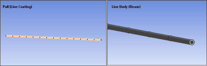
- Line Coating Display
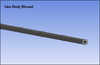
As illustrated, unlike beams, a Line Coating has no visible element expansion (no visible cross section). It displays as a line only.
As show, this also applies to stress and strain results scoped to a Line Coating. The result displays as a colored line.
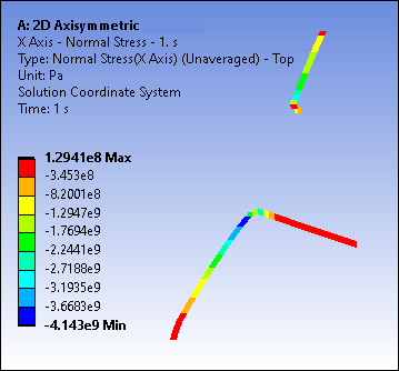
In addition, the Position property displays for stress and strain results scoped to a Line Coating. For the option , the application only displays Bottom results and generates an associated Message.
Important: When you use the Clear Generated Data option on Surface Coating or Line Coating Pull objects and regenerate them, the application retains the same Thickness property value on newly generated pull geometries – as well as before they were deleted. The application only supports this regeneration capability when the Stiffness Option property of the coating is set to Stress Evaluation Only. In addition, you must be in an active Mechanical session when you clear and regenerate Pull bodies for the thickness value to be retained.
When you have defined the desired type of pull, you select the context (right-click) menu option . This action creates the mesh of the corresponding extrude/revolve/coating. This action also creates a corresponding body, based on the pull type, under the Geometry object. You can then use this body as you would use any body for your analysis, however, because it was generated from mesh data, certain limitations exist. For example, if you encounter a scoping issue, try using mesh-based scoping, such as Element Face selection, to address such issues. See the Limitations topic below for more information.
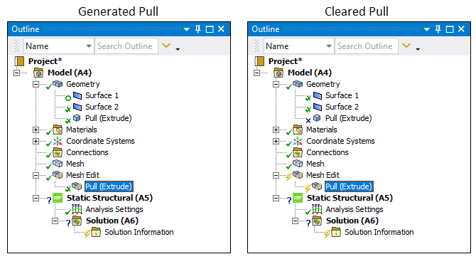
Note: When you scope a Pull object to a surface body and generate a 3D mesh using either the or method, the original surface body is marked as inactive using a circle symbol as shown below. This body becomes hidden in the Geometry window. The circle symbol also indicates an inactive body that does not participate in the analysis. The application does not write the body’s definition, or any Named Selections scoped to it, to the input file. In addition, the body does not contribute to the mass or volume of the geometry.
Background
The ability to create a volume mesh from a surface mesh is beneficial for the design and simulation of structures such as turbo machines and Printed Circuit Boards (PCB). It is common to first design a base surface, as it is easier to generate a surface mesh, and then to extrude a small layer of volume elements from this base mesh. Another example would be creating a 3D sector from a 2D surface body using the option and then perform a cyclic symmetry analysis. And you can scope the option to the face of a solid body and create a shell body whose mesh matches with the underlying solid body.
Application
See the Pull section of the Meshing User's Guide for a more detailed description about how to use this feature, its properties, and capabilities.
Limitations
The Pull feature is a mesh operation that generates volume mesh. Once created, you can scope the faces, edges, and vertices of the volume to other objects, such as loads, supports, and results. However, there are certain limitations associated with the pull-generated body as compared to an actual 3D body. Review the pull feature limitations listed below. You should also see the Pull section of the Meshing User's Guide for additional information.
Review the following feature limitations:
When you regenerate a Pull object, any other object scoped to geometric entities (face/vertex etc.) of the pull-generated body are reassociated. But any mesh-based scoping, such as element face or nodes, are automatically cleared.
Linear Periodic and Periodic Region objects are not supported when scoped to a body generated from the Pull operation.
If you scope a Pull body to a Cyclic Region, the Low Boundary property must be scoped to the face(s) adjacent to the original shell bodies and the High Boundary property must be set to the faces opposite to the Low Boundary in the direction of the Pull. Selecting any other faces may lead to a solver error.
You cannot scope Symmetry objects to Pull generated bodies in combination with the other bodies of your model.
Joint coordinate systems are not automatically oriented when scoped to Pull bodies.
Part Transformations are not supported for pull-generated bodies or the bodies scoped to a Pull object after it is generated. You must perform all transformations involving pull bodies prior to generation.
If you scope a load to a Pull body and need to specify a vector direction, use the Element Face selection to set the direction. Geometric entities are not supported for this capability.
Convergence is not supported when Pull objects are present in the model.
For a shell body generated using the > option, note the following limitations:
By default, when the application is creating the input file, the element adopts a full-integration scheme (KEYOPT(3) = 2) for low order mesh (element with no mid-side nodes). This is different than the Surface Coating feature specified via the Geometry object where (input file entries for) the element use the reduced-integration scheme (KEYOPT(3) = 0) for low order mesh. Therefore, you may see a difference between the results based on a Surface Coating created via Pull versus the Surface Coating feature specified via the Geometry object.
See the SHELL181 element section for more information regarding default KEYOPT(3) settings for shells.
The surface added using the Surface Coating is a separate part in the Geometry group rather than a multibody part with the solid body it was generated from. As a result, you cannot apply loads to vertices. You should apply the loads to the vertex of the underlying solid body.
If you set the Stiffness Option property of a Pull generated Surface Coating body to (default setting), loads using the setting for the Applied By property are not supported.
Because the surfaces of Pull generated bodies are constructed from the underlying mesh, you cannot scope spherical- and cylindrical-based boundary conditions, such as a Cylindrical Support or an Absorption Element, to these bodies.
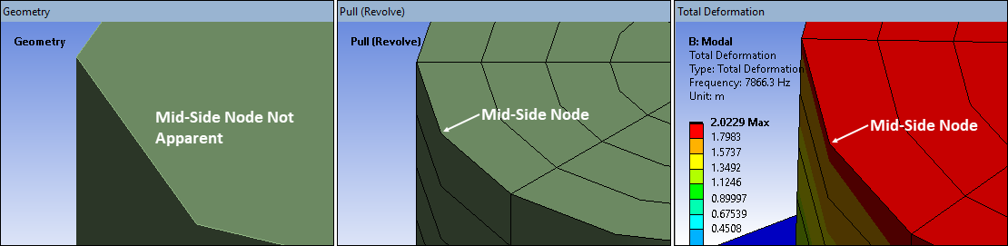
There is currently a display limitation for bodies generated using the > feature for higher order elements. You may notice when viewing a Pull Revolve generated body that it's geometric outlines does not appear to pass through the mid-side nodes of the generated mesh. This is a display issue and does not affect your results as illustrated below.