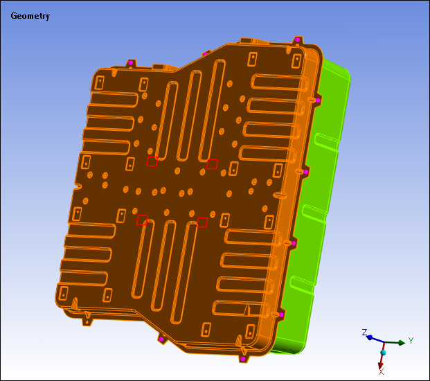
This section examines the following display features of the Geometry object.
Hide or Suppress Bodies
For a quick way to hide bodies (turn body viewing off) or suppress bodies (turn body viewing off and remove the bodies from further treatment in the analysis), select the desired body objects in the tree or select the bodies in the Geometry window (using the selection filter). Then right-click and choose or from the context menu. Choose , , , or to reverse the states.
The following options are also available:
: show only selected bodies.
or : contains menu options to hide specific body types. Based on the body types of your model, options include: , , and .
: This option inverts the visibility of hidden bodies versus those that are visible. That is, all hidden bodies become visible and all visible bodies become hidden.
, allows you to unsuppress only selected bodies.
Note:
If another model level object, such as a Remote Point, Joint, or Contact Region, is scoped to a Body that becomes Suppressed, that object also becomes suppressed until it is re-scoped or the body is Unsuppressed.
Results from hidden bodies are used in the formulation of the maximum and minimum values in the contour legend and in the Details View.
Results from suppressed bodies are suppressed and are not used in the formulation of maximum and minimum values.
Hide or Show Faces
You can hide selected faces on a model such that you are able to see inside the model. This feature is especially useful for bodies with interior cavities, such as engine blocks. To use the feature, first select faces on the model that you want to hide, then right-click anywhere in the Geometry window and choose Hide Face(s) in the context menu. This menu choice is only available if you have already selected faces.
Choose Show Hidden Face(s) from the context menu to restore the visibility of faces previously hidden using Hide Face(s). The Show Hidden Face(s) menu choice is only available if there are hidden faces from choosing Hide Face(s). It cannot be used to restore the visibility of faces previously hidden by setting Visible to No in the Details view of a Named Selection object.
Note: The selected faces will appear hidden only when you view the geometry. The feature is not applicable to mesh displays or result displays.
Color Coding of Parts
You can visually identify parts based on a property of that part. For example, if an assembly is made of parts of different materials, you can color the parts based on the material; that is, all structural steel parts have the same color, all aluminum parts have the same color and so on.
Select a color via the Display Style property of the Details view when the Geometry object is selected. You can specify colors based on:
(default): Assigns different colors to the bodies within a part.
: Assigns different colors to the different parts.
Shell Thickness (surface bodies only): Assigns different colors based on specified body thicknesses. This coloring property does not apply to imported thicknesses or Thickness object based specifications. For those specifications, use the display option of the Mesh object.
(Model assembly only): Assigns a common color to the bodies of each source system (assembly).
: The part colors are based on the material assignment. For example, in a model with five parts where three parts use structural steel and two parts use aluminum, you will see the three structural steel parts in one color and the two aluminum parts in another color. The legend will indicate the color used along with the name of the material. You can now assign colors to materials from the Outline Pane in the Engineering Data Workspace and have these colors display in Mechanical. For composite materials, the color assignment is program controlled.
Nonlinear Material Effects: Indicates if a part includes nonlinear material effects during analysis. If you chose to exclude nonlinear material effects for some parts of a model, then the legend will indicate Linear for these parts and the parts will be colored accordingly.
Stiffness Behavior: Identifies a part as Flexible, Rigid, or Gasket during analysis.
: This option assigns a color based on the different types of bodies within a part, such as beam and link types within a Line Body.
(line bodies only): The application assigns a color to a body based on its specified cross section.
(Rigid Dynamics analysis only): the application assigns colors per condensed part.
Note: A maximum of 15 distinct materials can be shown in the legend. If a model has more than 15 materials, coloring by material will not have any effect unless enough parts are hidden or suppressed.
You can reset the colors back to the default color scheme by right-clicking on the Geometry object in the tree and selecting .


