


Use the options described below to further define local mesh sizing. The choices that are available depend on the selected topology, physics preference, and as noted in the individual option descriptions. You can set the following local sizing options:
Definition Options:
Advanced Options:
Element Size
If you selected a body, face, or edge, (default) is one of the available options in the Type field. Enter a positive value (decimals are allowed) in this field. Smaller values generate more divisions. A value of "0" instructs the sizing control to use its defaults.
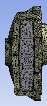
The following series of figures shows the effect of the option applied to the central face at 5mm.
| Element Size set to 5mm. |
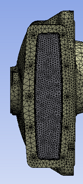 |
| Element Size default. |
 |
Additional details about the option differs depending on the sizing options set. The description of is as follows:
For an edge, is the maximum size on the edge. It takes priority over the global Max Size, and any face or body sizing control that includes the edge(s). If two edge sizing controls are attached to the same edge, the latter size control takes priority.
For a face, is the maximum size on the face, which is then propagated down to the edges (unless a more local edge control is assigned). The value of takes priority over Max Size and any body size control that includes the face(s). If two face sizing controls are attached to the same face, the latter size control takes priority.
For a body, is the maximum size on the body, and the maximum sizes on faces and edges of the body (unless a more local face or edge size control is assigned). The value of takes priority over the global Max Size. If the body size behavior is Hard, the value of also takes priority over the global Max Size.
Sphere of Influence
The option is available in the Type field after you select an entity such as a body, face, edge, or vertex.
If the Sphere of Influence is scoped to a body or vertex, the Sphere of Influence affects the entire body regardless of sizing options being used. If the Sphere of Influence is scoped to a face or edge and Use Adaptive Sizing is set to Yes, the Sphere of Influence only affects the face(s) or edge(s) that are scoped to the control and the transition away from those entities. If the Sphere of Influence is scoped to a face or edge and any other sizing option is used, the Sphere of Influence will affect the whole body (not just scoped face(s) or edge(s)).
Although the Behavior option is not available for , behaves as a Hard setting. That is, in the vicinity of a , the sizing overrides pre-existing sizing information regardless of whether the pre-existing sizes are larger or smaller than the sizing. This is in contrast to the option, which behaves as a Soft setting.
For bodies, faces, and edges, allows you to apply mesh sizing within the confines of a sphere in space that you define as follows:
Create a local coordinate system whose origin you intend to be the center of the sphere.
Select this coordinate system in the Sphere Center field.
Enter the radius of the sphere in the Sphere Radius field.
Enter a value in the Element Size field. The element size will be applied to all topologies within the confines of the sphere. For example, if you are applying the element size to a face, the size will also be applied to the edges of that face, and to the vertices of those edges, but only within the confines of the sphere. An example is shown below.
 |
 |
If you selected a vertex, the only option available in the Type field is . The description is the same as presented above except that the center of the sphere is the vertex. There is no need to create or use a local coordinate system to define the center of the sphere. After applying element size to a vertex using , the element size is applied to all topologies connected to that vertex, such as all edges and faces containing that vertex, if they fall within the sphere. An example is shown below.
 |
 |
Body of Influence
The option is available in the Type field if you selected a body and Use Adaptive Sizing is set to No. Using this option, you can set one body as a source of another body (that is, a ). The will influence the mesh density of the body that it is scoped to, but it will not be a part of the model geometry nor will it be meshed. bodies are noted in the Details View of each prototype.
Although the Behavior option is not available for , behaves as a Soft setting. That is, in the vicinity of a , the specified sizing must be larger than the smallest Curvature Min Size/Proximity Min Size and smaller than the global Max Size to have an effect on the mesh size distribution. The specified sizing imposes a local maximum size on all elements that are inside the boundary of the body. This is in contrast to the option, which behaves as a Hard setting.
Remember the following notes when using :
If your source body is a sphere, it is best for you to use the option instead of . is intended for non-spherical bodies.
In general, users are discouraged from defining a and a such that the regions of influence overlap. In cases where elements fall within overlapping bodies/spheres of influence, elements will be created using the sizing that appears lowest in the Tree.
You cannot apply loads, mesh controls, etc. on bodies of influence. Bodies of influence are used only to influence the sizing controls and therefore only sizing attributes can be applied to them.
You can suppress and unsuppress bodies of influence.
If you are using with Match Control, be aware that the body of influence will not be copied from one matched entity to the other. As a workaround, you can copy the body in the DesignModeler application and use both bodies as your source.
Factor of Global Size
If you select a body, face, or edge, is one of the available options in the Type field (unless Use Adaptive Sizing is set to Yes). Choose and enter a value for to define the local minimum and defeature sizes as factors of the global element size. If local sizings are defined as a factor of global size and you modify the Element Size, the local sizings are recalculated.
Number of Divisions
If you select an edge, the options available in the Type field are and , along with the option. Choosing and entering a value in the Number of Divisions field is an alternative to choosing if you are interested in having the mesh be sized according to a discrete number of divisions along an edge. If you set to a value greater than 1000, the number of divisions will not be drawn on the edge in the Geometry window.
Defeature Size
For body sizing and face sizing controls, sets the local tolerance for defeaturing. Features smaller than or equal to this value will be removed when the mesh is generated. You can specify any value greater than 0.0.
If the local sizing is Uniform, the default local Defeature Size is set to the smaller of the following two values:
Global Defeature Size
50% of the value of the local Element Size
For all other local sizing controls, the default local Defeature Size is set to the smaller of the following two values:
Global Defeature Size
50% of the value of the local Curvature Min Size or Proximity Min Size (whichever is smaller)
For more information about setting the defeature size, see Defeature Size.
Defeature Size Scale
Specify the scale factor for the defeature size. The default values comes from the scale factors for Mechanical Defeature Size Factor and CFD Defeature Size Factor depending on the physics preference (CFD physics preference uses the CFD Defeature Size Factor, other physics preferences use the Mechanical Defeature Size Factor). The default value or the value that you specify is multiplied by the global element size to determine the local defeature size.
Influence Volume
When Element Size is selected, the Influence Volume appears with Yes or No option. The default option is No. If you select Yes, the Affected Distance field appears. When influencing the volume, the face size control generates spheres of influence internally by automatic determination of radius and size based on the Affected Distance.
Note:
Cartesian method does not support Influence Volume meshing.
Layered Tetrahedrons Method does not support Influence Volume meshing.
When Adaptive Sizing is set to Yes, Influence Volume option does not have effect.
Affected Distance
When Influence Volume is set as Yes, the Affected Distance option appears. You can enter the distance up to which the defined Element Size will affect the volume mesh.
Capture Curvature and Capture Proximity
If a global sizing option is defined for the model, then you can set a local sizing on a body, face, or edge to further refine the local entity's sizing. When you set a local sizing on an entity, the local sizing options default to the same values that are defined for the global size function. You can change any of these values, and the local values will take precedence over the global values when the mesh is generated.
For example, if Capture Curvature and/or Capture Proximity are selected, and the local sizing is Uniform (or vice versa), the local sizing option takes precedence.
Example 4: Setting a Local Sizing Option
If the global sizing option is set to Curvature with a 20° Curvature Normal Angle, and you set a local sizing of Curvature on a face with a 60° Curvature Normal Angle, the local Curvature Normal Angle will take precedence when the mesh is generated. In this example, the face with the local sizing control will use a Curvature Normal Angle of 60° even though the global value is 20°.
If using Nonlinear Mechanical or CFD physics preference, or when Use Adaptive Sizing is set to No; the following options are available and work as follows:
Capture Curvature = Yes turns on the Curvature-based Sizing.
Capture Proximity = Yes turns on the Proximity-based Sizing.
If Capture Curvature and Capture Proximity are both set to Yes, then both Curvature-based Sizing and Proximity-based Sizing will be used.
If Capture Curvature and Capture Proximity are both set to No, then Uniform sizing will be used.
Note: Local sizing limitations include:
If Use Adaptive Sizing is set to Yes, then you cannot set a local size function.
If the global sizing option is set to Capture Proximity or both Capture Proximity and Capture Curvature, and the local sizing option is set to Capture Curvature or both Capture Proximity and Capture Curvature (or vice versa), the mesh on the entity is generated as though both Capture Proximity and Capture Curvature are set locally.
If the global sizing option is set to Capture Proximity, and the local sizing option is set to Capture Curvature (or vice versa), the option that has the smallest size specified for it (either Proximity Gap for the Proximity sizing, or Curvature Normal Angle for the Curvature sizing) takes precedence.
The local Proximity sizing is not supported for sheet models. If both the local Proximity and Curvature sizing is defined on a sheet model, only the Curvature sizing takes effect.
Local proximity sizing is not supported for edge sizing controls. To set a local edge sizing control, you must choose either Capture Curvature or Uniform (both Capture Curvature and Capture Proximity set to No).
Growth Rate
You may specify a growth rate for the scoped soft size of an entity (body, face, or edge only). The description of the scoped Growth Rate is the same as that of the global growth rate that you can set in the Details View when the Mesh object is selected in the Tree Outline. However, the growth rate you specify for a scoped entity must always be smaller than or equal to the specified global growth rate. Growth Rate is not available for Sphere of Influence. Specifying a growth rate for a face or body affects the growth on the face or on the boundary of the body, and its effect continues outside of the scoped entity as well.
Local Min Size
You can set Local Min Size to specify a value that takes priority over the global Min Size when you select a body, face, or edge. If Local Min Size is set to Default, the mesher uses either the global Min Size or the local Element Size (if defined), whichever is smaller. This setting is available when Capture Curvature is set to Yes, and is useful when you want to refine the mesh based on curvature. When you set the Local Min Size, the mesher refines from the Element Size to the Local Min Size in curved areas, but retains the Element Size for flat areas.
Note: Local Min Size may not be respected by the Sweeping or MultiZone Methods due to the interval assignment used to generate structured meshes. The min size is used on source faces, but not necessarily on side faces.
Curvature Min Size Scale
Specify the scale factor for the curvature minimum size. The value that you specify is multiplied by the global element size to determine the local curvature minimum size. The default is determined by the Mechanical Min Size Factor or CFD Min Size Factor option in the Options dialog box, depending on the physics preference.
Curvature Normal Angle
You may specify Curvature Normal Angle for a scoped entity (body, face, or edge only). Curvature Normal Angle is the maximum allowable angle that one element edge is allowed to span given a particular geometry curvature. Available only when Capture Curvature is set to Yes. You can specify a value from 0 to 180 degrees to override the global setting (where a value of 0 resets the option to its default). The default for the global setting is calculated based on the Physics Preference.
For more information, see Curvature Normal Angle.
Proximity Min Size
This option allows you to specify a minimum size to be used in a local proximity sizing calculation, in addition to the Local Min Size. By default, Proximity Min Size is set equal to the default of Local Min Size. You can accept the default or specify a value greater than 0. For more information, see Proximity Min Size.
Proximity Min Size Scale
Specify the scale factor for the proximity minimum size. The value that you specify is multiplied by the global element size to determine the local proximity minimum size. The default is determined by the Mechanical Min Size Factor or CFD Min Size Factor option in the Options dialog box, depending on the physics preference.
Proximity Gap Factor
Specify the minimum number of layers of elements to be generated in gaps when Capture Proximity is set to Yes.
Proximity Size Function Sources
This option is available if Capture Proximity is set to Yes. It determines whether regions of proximity between faces and/or edges are considered when proximity sizing calculations are performed.
For more information, see Proximity Size Function Sources.
Behavior
If the global option Use Adaptive Sizing is Yes, or the local sizing is Uniform (both Capture Curvature and Capture Proximity set to No), the Behavior option is available for bodies, faces, and edges.
You can specify either Soft (default) or Hard, but the effect depends on the type of mesh being generated. Typically, Hard results in a stricter size setting than Soft. For example, with a tri or tet mesh, the Hard setting would not allow as much transition from one element size to another element size due to influences of sizing on neighboring objects. With a Hard setting, the element size defined would be maintained for the object to which the setting is scoped. With a Soft setting, the element size defined may be modified in order to respect other size settings in the vicinity of the object to which the setting is scoped.
You should take care when applying Hard sizes. With a mapped quad/tri or swept mesh, a Hard setting forces the interval edge assignment on the object to be met, and if the mesher cannot achieve the setting, the mesh could fail.
Bias Type and Bias Option
For edges only, use Bias Type to adjust the spacing ratio of nodes on an edge. This feature is useful for any engineering problem where nodes need to be clustered on an edge or group of edges, or if there is a need to bias the mapped mesh of a face towards a specific direction with respect to the edges of the face. Bias Type can be used with all meshers except the Patch Independent Tetrahedron method. To use Bias Type, choose one of the four pre-determined patterned options depicted pictorially from the Bias Type drop-down menu:
Note: The MultiZone meshing method respects all Bias Type options. The nodes generally follow the distribution. However, some optimization can be done to improve transition with other mesh, or to improve the quality. Setting the Behavior to Hard will give higher priority to the bias settings defined than the optimization.
Then specify a Bias Option. The drop-down menu enables you to choose No Bias, Bias Factor, or Smooth Transition:
Bias Factor is defined as the ratio of the largest edge to the smallest edge. To set the Bias Factor, choose Bias Factor from Bias Option and enter a value into the field to define the ratio.
Smooth Transition is defined as Growth Rate = Bias Factor^(1/(n-1)), where n is the number of divisions. To define Smooth Transition, choose Smooth Transition from Bias Option, then enter a value for Growth Rate.
Note: If Behavior is set to Hard, then the number of divisions and the bias cannot be changed by the mesher. If Behavior is set to Soft, then the edge divisions can be changed but the edge will be initially meshed with the specified Bias Factor.
If you want to select multiple edges to apply sizing, but some of the edges do not have the same orientation, you can use the Reverse Bias option to manually select all of the edges. Reverse Bias is available when the control is applied to the edges, defined as an Element Size or Number of Divisions, and has a bias towards one of the vertices (“- -- --- ----” or “---- --- -- -”).
To apply Reverse Bias, select a group of edges, then choose Reverse Bias and click Apply. Only edges that are part of the main scoping of the control are applied. All others are ignored.
To undo Reverse Bias, select an edge that is not part of the main scoping. Then choose Reverse Bias and click Apply.