


Mechanical enables you to export specifically supported analysis data to one or more of the following file types. Review the following topics based upon the desired export file format.
See the Options Settings topic at the end of the section for some general export settings that are available using the Options dialog.
General Export Procedure
Select an object in the tree.
Click the Worksheet to give it focus (if applicable).
Right-click the selected object in the tree or on a selection in the Tabular Data window, select , and then select a file type as required.
Specify a file name and save the file. Based on the object type, the application may automatically open Excel, assuming you have the application.
Note: You must right-mouse click the selected object in the tree to use this feature. On Windows platforms, if you have the Microsoft Office 2002 (or later) installed, you may see an option if you right-mouse click in the Worksheet. This is not the Mechanical application feature but rather an option generated by Microsoft Internet Explorer.
Exporting to Text and Delimited Files
You can export a variety of analysis data to a tab-delimited text file. This file format enables you to view the data in a text editor as well as Microsoft Excel. Mechanical supports exporting data from the following object types (without access to worksheet data):
Additionally, data from the following additional objects can be exported but requires worksheet data to be active:
| Connections | Convergence | Geometry |
| Contact Group | Coordinate Systems | Mesh |
| Contact Initial Information | Fatigue Sensitivities | Solution |
| Contact Tool | Frequency Response | Thermal Condition |
Stereolithography (STL)
The following objects enable you to export object information in STL file format, either as Binary (default) or ASCII. File size is the primary difference between the file formats. The binary format generates smaller files, however; it does not include information for the bodies of your model. The ASCII format preserves all body information during export. Using the Options dialog box, under the Export category, you can change the default setting for exporting in STL format.
Important: Mechanical obtains unit data from imported CAD models and displays the unit in the Length Unit property of the Geometry object. This is the unit system used by the STL export feature. When opening your exported STL file in a CAD application, make sure that the application is also using this unit system. For example, in SpaceClaim, set your unit system by selecting File > SpaceClaimOptions > File Options > STL, and then specify the appropriate unit system from the Units drop-down menu.
Note:
When a model contains multiple bodies, Mechanical uses a nonstandard file format for the ASCII representation. In this case, the application separates the bodies.
Files saved in the STL format can be viewed in appropriate STL supported applications, such as SpaceClaim. Currently for the Mesh object and for results-based objects (not including contour data), files exported in the ASCII format enable you to render individual parts of your model in SpaceClaim. Files in the binary format do not support this display capability.
The display of an exported STL file, regardless of viewer type, is based on the scale you specify in the Result drop-down menu, on the Solution Context tab. That is, if the scale is set to show deformations, the model is exported in the deformed shape.
When you select Top/Bottom as the Shell setting in the Details view for a surface body and export the result contours (such as stresses and strains), the export file contains two results for every node on a shell element. The first result is for the bottom face and the second result is for the top face.
Ansys Viewer File (AVZ)
Mechanical enables you to export your mesh and/or a result object as an AVZ (.avz) file. The export operation creates a 3D model representation that you can display in the Ansys Viewer (installation required). The Ansys Viewer is a WebGL based 3D image viewer that you can use to visualize the exported mesh and results of your analysis without opening the Mechanical application. For results, you can inspect result values at specific locations by hovering the mouse over a point on your model. For result objects and as desired, you can automatically launch the Ansys Viewer by changing the default setting under the Export preference of the dialog.
Note: Exporting results that include a customized legend may present legend/contour display inconsistencies in the viewer.
Geometry (Part Manager Database)
You can export the geometry (entirely or as parts) to a binary Part Manager Database (.pmdb) file by:
Right-clicking on the Geometry object and then selecting >. The application writes the entire geometry to the .pmdb file. This option also writes any Named Selections created in Mechanical into the .pmdb file.
Or...
Right-clicking one or more bodies/parts, and then select >. The application writes the selected parts to the .pmdb file. If a selected body is part of a multi-body part, then the entire part is written to the file.
Or...
Right-clicking one or more bodies in the Geometry window and then selecting >. The application writes the selected parts to the .pmdb file.
Part Manager Database Requirements and Limitations
Exporting the Geometry as a .pmdb file facilitates future geometry import into SpaceClaim, DesignModeler, as well as re-importing the file back into Mechanical.
When exporting a geometry to a .pmdb file, the application exports all bodies, including suppressed bodies, to the file without maintaining their suppression status. Therefore, when you re-import the geometry, all of the bodies are unsuppressed. However, the application does export whether or not a you have hidden bodies. This means that suppressed bodies, which are typically hidden, appear hidden when you re-import the geometry. As a result, your geometry may have bodies that are hidden, because they were suppressed on export, but that are no longer suppressed.
The application does not export supplemental model data created after the geometry was imported. This includes coordinate systems, work points, spot welds, or materials that you manually added during your Mechanical session.
When defined, .pmdb files include geometry cross sections for line bodies in the exported file. Subsequent SpaceClaim and Mechanical sessions import the line body cross section data accordingly. However, DesignModeler does not support importing line body cross section data and as needed, requires you to redefine the cross sections if imported into DesignModeler.
For any of the following that are exported as a Part Manager Database (.pmdb) file and then imported into a new Mechanical session, the application does not currently support re-meshing using normal mesh methods:
Geometries created from External Model
Deformation results
Parts created using the Mesh Pull feature
NASTRAN Bulk Data
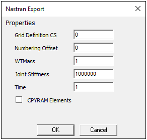
For Static Structural and Modal analyses, you can export your simulation as a NASTRAN Bulk Data (.bdf, .dat, .nas) file.
When you select the Environment object, the option, Export NASTRAN File is available in the Tools group of the Environment Context Tab. Based on your analysis type, one of the following dialogs displays. You use these property options to further define how you wish to export your simulation.
Note: Also see the Writing NASTRAN Files section for the steps to export your analysis as a NASTRAN (.nas) file.
Ansys Sound
Mechanical enables you to export a result to Ansys Sound software for sound synthesis, sound design, or psychoacoustics analysis. When exporting the result, the data is stored in an XML file, then Ansys Sound SAS is opened (if installed on the machine) and automatically opens this file. The option is supported for the following acoustics results:
Equivalent Radiated Power Level
ERP Level Waterfall Diagram
Frequency Response Sound Power Level
Far-field SPL Mic (when the property is set to )
Far-field Sound Power Level
Far-field Mic Waterfall Diagram
Far-field Sound Power Level Waterfall Diagram
For more information, see the Ansys Sound documentation.
Waveform Audio File (WAV)
You can export the following acoustic-based result types to a Waveform Audio File (.wav) file:
Equivalent Radiated Power Level
ERP Level Waterfall Diagram
Frequency Response Sound Power Level
Far-field SPL Mic (when the property is set to )
Far-field Sound Power Level
Far-field Mic Waterfall Diagram
Far-field Sound Power Level Waterfall Diagram
Note: Waterfall result types are only supported by the Harmonic Model sampling method described below.
For the above result types, the context (right-click) menu option > opens the preference window shown below. The default settings are displayed.
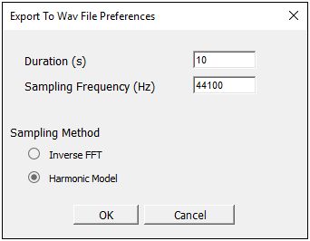
The Duration and Sampling Frequency options are basic settings that enable you to specify the duration and sampling frequency of the audio file.
The Sampling Method options include:
Inverse FFT (Fast Fourier Transform): This method generates a sound from a given spectrum using a Fourier transform. This method creates a sound sample based on the given input spectrum (level vs. frequency). This resulting sound sample has the same spectrum as the input. This method is recommended for broadband noise spectrum.
Harmonic Model: This method generates a sound from a spectrum using sound synthesis from sinusoidal patterns. This method creates a sound sample based on the given input spectrum (level vs. frequency) that contains harmonic components at the same exact frequencies specified in the input spectrum. Each frequency has the same level as the specified input. This method is recommended for pure tones sounds.
Options Dialog Settings
The Export category of the Options dialog includes the following preferences that apply to exporting data.
| Automatically Open Excel (Yes by default) |
| Remove Duplicate Nodes (No by default) |
| Include Node Numbers (Yes by default) |
| Include Node Location (No by default) |