


Represents the inertial effects from a body.
 |
Object Properties
The Details Pane properties for this object include the following.
|
Category |
Properties/Options/Descriptions |
|---|---|
|
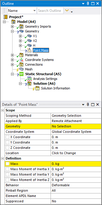
Scope |
Scoping method: Specify as Geometry Selection (default) or Named Selection or Remote Point (only available when a user-defined Remote Point exists in the tree). Geometry: Visible when the Scoping Method is set to Geometry Selection. Displays the type of geometry (Body, Face, etc.) and the number of geometric entities (for example: 1 Body, 2 Edges) to which the boundary has been applied using the selection tools. Use selection filters to pick geometry, click in the Geometry field, then click . The Remote Attachment option is the required Applied By property (see below) setting if the geometry scoping is to a single face or multiple faces, a single edge or multiple edges, or multiple vertices. Named Selection: Visible when the Scoping Method is set to Named Selection. This field provides a drop-down list of available user–defined Named Selections. Remote Points: Visible when the Scoping Method is set to Remote Point. This field provides a drop-down list of available user–defined Remote Point. Applied By: Specify as Remote Attachment (default) or Direct Attachment. Coordinate System: Aligns the inertial axes of the Point Mass with a local coordinate system. The local system must have been previously defined by one or more Coordinate System objects. For the Rigid Dynamics and Explicit Dynamics solvers, the Mass Moment of Inertia axes also align to this coordinate system. For the Mechanical APDL Solver, by default, the Mass Moment of Inertia axes align to the Global Coordinate System. X Coordinate: Define X coordinate location. You can set this property as a parameter. Y Coordinate: Define Y coordinate location. You can set this property as a parameter. Z Coordinate: Define Z coordinate location. You can set this property as a parameter. Location: Change location of the load. Pick new location, click in the Location field, then click . |
| Definition |
Mass: Define mass; can be designated as a parameter. Mass Moment of Inertia X: Available for 3D models only. Mass Moment of Inertia Y: Available for 3D models only. Mass Moment of Inertia Z: Available for 3D models only. Material: Available when the Behavior property is set to . Select a material to define material properties for the beams used in the connection. Density is excluded from the material definition. Radius: Available when the Behavior property is set to . Specify a radius to define the cross section dimension of the circular beam used for the connection. Element APDL Name: Optional property that enables you to manually define an APDL parameter (in the input file) and assign the parameter value as the element of the Point Mass. This facilitates easy programmatic identification of the element of the Point Mass for later use/reference in a Commands (APDL) object. |
Tree Dependencies
Insertion Methods
Use any of the following methods after selecting the Geometry object or a Body object:
Select the option from the Mass group on the Geometry Context tab.
Right-click and select > .
Right-click Options
In addition to common right-click options, relevant right-click options for this object include:
>
Promote Remote Point (Remote Attachment Only)
API Reference
See the Point Mass section of the ACT API Reference Guide for specific scripting information.
Additional Related Information
Point Mass application
Geometry Context Tab