


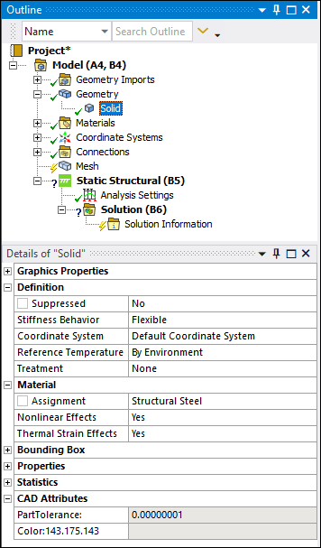
Defines a component of the attached geometry included under the Geometry object, or under a Part object if considered a multibody part (shown in the figure below).
 |
Object Properties
The Details Pane for this object includes the following properties.
| Category | Properties/Options/Descriptions | |||||||||||||||
|---|---|---|---|---|---|---|---|---|---|---|---|---|---|---|---|---|
|
Graphics Properties |
The following properties change the graphical display of a body.
| |||||||||||||||
|
Definition |
Dimension (Surface Bodies Only): Specify the selected surface body as either three-dimensional or two-dimensional. Options include (default) and . For multi-body parts, you can specify each body independently as either 3D or 2D. When you set this property to , the application automatically displays the 2D Behavior property. Supported settings for the 2D Behavior property include , , , and . Note: The application automatically clears and regenerates the mesh when you change the setting of this property. This default behavior can be turned off using the Options dialog. Set the Clear Mesh on Dimension Change property, under the Geometry category, to .
Stiffness Option (Surface Bodies Only): Specifies the element stiffness for 3D flexible shell bodies. It is only applicable to analysis types where the Physics Type property of the environment object is set to . In addition, for the property to be visible, the Stiffness Behavior property must be set to , and the Dimension property must be set to . Property options include (default), , and . Note: See the Help sections for the elements SHELL181 and SHELL281 (for KEYOPT(1)) in the Element Reference for additional information. Note the following additional requirements:
Brick Integration Scheme: Appears only if Element Control is set to Manual in the Details pane of the Geometry object; not available if Stiffness Behavior is set to . Coordinate System: Assign a local coordinate system to specify the alignment of the elements of the body if previously defined using one or more Coordinate System objects; not available if Stiffness Behavior is set to . Reference Temperature Value: Available only when you select By Body as the Reference Temperature. Reference Frame: Only appears when an Explicit Dynamics system is part of the solution. Thickness: Appears only for a Surface Body. Thickness Mode: Appears only for a Surface Body and is a read-only indication. Cross Section: Appears for line bodies only. Provides a drop-down menu of selectable cross section options/objects. Offset Mode: Appears only for a Line Body. Offset Type: Appears for Line Bodies and for Surface Bodies when 1) the Dimension property is set to and 2) the Model Type property is set to . Model Type: Displays for line bodies and surface bodies when the Dimension property is set to .
See the Reinforcement Specification Using Mesh-Independent Method section for information about using the For Reinforcement setting. 2D Behavior: Available when:
Treatment: Generally used to scope a surface body to an Arbitrary Crack (via the Crack Surface property) or a line body to a Spot Weld, this property includes the options (default) and . When you set the Treatment property to , the associated Body is not recognized during the mesh or solution process. Important:
| |||||||||||||||
|
Material |
Assignment: Specify a desired material for the body. This property can be designated as a parameter. Nonlinear Effects: Not available if Stiffness Behavior is set to . Gasket Initial Gap: Only displays when a valid Gasket
Material is assigned and enables you to specify an initial gap for a gasket. The
default value is Fluid/Solid: Available only in the Meshing application (that is, not available if you are using the meshing capabilities from within the Mechanical application). Allows you to control the physics that occur on a model. Valid options are Fluid, Solid, and Defined By Geometry. When set to Defined By Geometry, the value is based on the Fluid/Solid material property that was assigned to the body in the DesignModeler application. | |||||||||||||||
|
Length X Length Y Length Z | ||||||||||||||||
|
Properties: Indications of the properties originally assigned to the body. |
Volume Mass Length: Appears only for line bodies.
Note:
The following appear for all bodies except line bodies:
Note: Surface bodies are dependent upon the 2D Behavior setting of the Geometry object. Any setting other than the setting causes the above properties, except Surface Area, to display with the content "N/A" (Not Applicable) in their field. However, when the 2D Behavior property is set to , you can change the setting of the 2D Behavior property for each surface body individually. These individual settings affect what is displayed by a property’s field. Based on the setting of the Model Type property, the following may appear for line bodies:
The following appear for surface bodies only:
| |||||||||||||||
|
Statistics |
The properties of this category provide a read-only indication of the entities that comprise the body. Nodes Elements Mesh Metric |
Tree Dependencies
Insertion Methods
Appears by default when a geometry is attached.
Right-click Options
In addition to common right-click options, relevant right-click options for this object include:
>
>
Export >
or > // (option availability based on body type)
Update Selected Parts > Update: Use Geometry Parameter Values
API Reference
See the Body section of the ACT API Reference Guide for specific scripting information.
Additional Related Information
See the Attach Geometry/Mesh section for the methods to open a geometry in Mechanical.
Note: When a Surface Body is meshed with the SHELL181 element, KEYOPT(3) = 2 (full-integration scheme) is written to the input file. This differs from the usual default setting for SHELL181, KEYOPT(3) = 0 (reduced integration). Note that this element is a lower order element and is only used when the Mesh object property Element Order is specified as , either by you as the user or by the application. See the Mechanical APDL Element Reference for SHELL181 for more information.