


Imports shell thickness data from external files. You import thickness data into Mechanical by:
Linking the Model cell of a supported system to the Setup cell of an upstream External Data system in the Project Schematic and opening the Mechanical from Workbench. Once open, the application automatically inserts an Imported Thickness folder in the Outline as well as an Imported Thickness child object. See the steps in the Importing Data section of the External Data System documentation for the steps to configure your systems in Workbench.
Using the Imported Thickness option of the Geometry object context toolbar in Mechanical. This option is also available from the context (right-click) menu option Insert of the Geometry object as well as the context menu of the geometry window. When selected, the application automatically inserts an Imported Thickness folder in the Outline as well as an Imported Thickness object.
Solver Notes:
For the Mechanical APDL solver, thickness on 3D shells is represented at the nodal level via the SECFUNCTION command. For 2D plane stress, thicknesses are calculated as an average value from the element's nodal thickness values and it is input as a real constant for the element.
For the Explicit Dynamics solver the element's nodal thicknesses are converted to an average element thickness.
For the LS-DYNA solver, thicknesses are applied to the nodes. This is also true for 2D analyses.
Applies to: Imported Thickness object folder and all thickness child objects under the folder.
 |
Object Properties
The common Details properties are listed below. Additional properties may be included. See the Appendix B. Data Transfer Mesh Mapping section for additional information about other categories, such as Settings, Graphics Controls, etc.
| Category | Properties/Options/Descriptions |
|---|---|
|
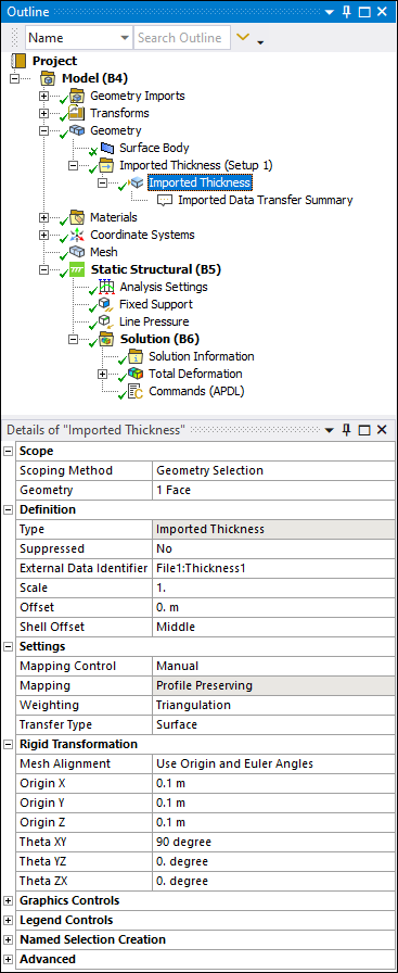
Scope |
Scoping Method: Options include Geometry Selection or Named Selection. Geometry: Appears if Scoping Method is set to Geometry Selection. In this case, use selection filters to pick geometry, click in the Geometry field, then click Apply. Named Selection: Appears if Scoping Method is set to Named Selection. Specify a desired Named Selection from the drop-down list. |
|
Definition |
Type: Read-only field that describes the object - Imported Thickness. Suppressed: Select Yes to suppress Imported Thickness. External Data Identifier: Choose the appropriate data identifier which represents the thickness data from the file. Scale: The amount by which the imported thickness values are scaled before being used for display or solution. Offset: An offset that is added to the imported thickness values before being used for display or solution. Shell Offset: Enter an offset value as desired. |
|
Advanced |
Unmapped Data Value: You can specify a thickness value for the unmapped target nodes using the Unmapped Data Value property. By default, a zero thickness value is assigned to the unmapped nodes. For the Ansys solver, the thickness value at each node must be greater than zero. See External Data in the Mechanical User's Guide for details. |
Tree Dependencies
Valid Parent Tree Object: Imported Thickness group.
Insertion Methods
Automatically generated from Workbench configured systems.
Select the Geometry object and select the Imported Thickness option from the Shells group on the Geometry Context Tab. You can also right-click the Geometry object, or within the Geometry window, and select > Imported Thickness.
Right-click the Imported Thickness group object and select > Thickness.
Select the Imported Thickness group folder and then select the option on the Imported Fields Context tab.
Right-click Options
In addition to common right-click options, relevant right-click options for this object include:
API Reference
See the Imported Thickness section of the ACT API Reference Guide for specific scripting information.
Additional Related Information
See the following sections for more information: