


Define the individual loads, supports, and conditions used as boundary conditions in the environment for a model.
Applies to the following objects: Absorption Element, Absorption Surface, Acceleration, Bearing Load, Bolt Pretension, Compression Only Support, Conductor, Constraint Equation, Contact Step Control, Convection, Coupling, Current, Cylindrical Support, Detonation Point, Diffuse Sound Field, Displacement, Elastic Support, Far-Field Radiation Surface, Nodal Displacement, Nodal Rotation, Free Surface, Fixed Rotation, Fixed Support, Fluid Solid Interface, Force, Frictionless Support, Generalized Plane Strain, Heat Flow, Heat Flux, Hydrostatic Pressure, Impedance Boundary (Explicit Dynamics), Impendance Boundary (Acoustic), Impedance Sheet, Imported CFD Pressure, Incident Wave Source, Internal Heat Generation, Mass Flow Rate, Joint Load, Limit Boundary, Line Pressure, Low Reduced Frequency Model, Magnetic Flux Parallel, Mass Source, Moment, Nodal Orientation, Nodal Force, Nodal Pressure, Geometry Based Adaptivity, Nonlinear Adaptive Region, Element Birth and Death, Perfectly Insulated, Pipe Idealization, Pipe Pressure, Pipe Temperature, Plastic Heating, Port, Pressure, Pressure (Acoustic), Port In Duct, PSD Base Excitation, Radiation, Radiation Boundary, Remote Displacement, Remote Force, Rigid Wall, Rotating Force, Rotational Acceleration, Rotational Velocity, RS Base Excitation, Simply Supported, Standard Earth Gravity, Static Pressure, Surface Velocity, Symmetry Plane, System Coupling Region, Temperature (Acoustic), Temperature, Thermal Condition, Thermo-Viscous BLI Boundary, Transfer Admittance Matrix, Velocity, Viscoelastic Heating, and Voltage.
Support object for a Static Structural analysis: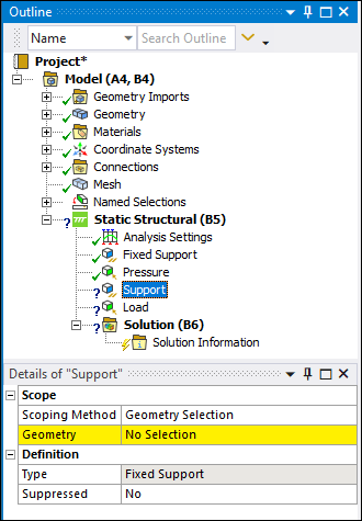 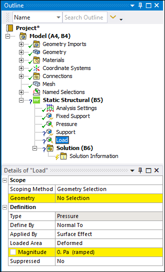 |
Object Properties
See the Applying Boundary Conditions section for more information about Loads, Supports, and Conditions.
Tree Dependencies
Valid Parent Tree Object:
For Magnetostatic Analysis only: Source Conductor when specifying a Current or Voltage.
For all other objects: An analysis environment object.
Valid Child Tree Objects:
Insertion Methods
For Current or Voltage, scope to a body, then use any of the following methods:
Select Conductor or Current on the Environment Context Tab, then select Current or Voltage.
Right-click the Magnetostatic object, or in the Geometry window then or Voltage.
For all other objects, use any of the following methods after highlighting Environment object:
Choose Inertial, or Load, or Supports, or on Environment Context Tab.
Right-click the Environment object, any load, support, or condition object, or in the Geometry window .
Right-click Options
In addition to common right-click options, relevant right-click options for this object include:
Promote to Named Selection: Available for most boundary condition objects. It enables you to create a Named Selection based on the scoping of the load. It also automatically changes the Scoping Method of the load to Named Selection and automatically specifies the newly created Named Selection in the scoping.
: Available for Bolt Pretension loads scoped to one or more Edges, Faces, or Element Faces that have the accompanying Coordinate System Behavior property set to . The option enables the application to calculate and define the internal coordinate system for this feature.
When you promote a Coordinate System, the application automatically 1) adds a new Coordinate System object the to Coordinate Systems folder, 2) sets the Coordinate System Behavior property to , and 3) specifies the newly promoted Coordinate System to the scoping.
Additional Related Information
See the following sections for more information: