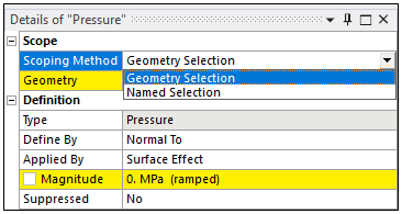
Almost every boundary condition available in the application has a Details group, Scope, that includes the property Scoping Method. A Pressure load is illustrated below. Scope refers to the geometry over which a boundary condition is applied. You can select geometry or geometries of your model using geometry selection tools () or through the use of the feature. You "scope" boundary conditions to geometric entities (bodies, faces, edges, or vertices), and depending upon the load type, mesh entities (nodes, element faces, and elements).

For example, if you apply a force of 1000N in the X-direction to a vertex, the load is "scoped" to that vertex.
Scoping Method Techniques
The application provides several common methods for scoping boundary conditions. Regardless of the method you choose, you need to select geometry entities of the model and scope those entities with a boundary condition. The order of these selections can vary.
You can first select a boundary condition and then specify a geometry:
Highlight the Environment object.
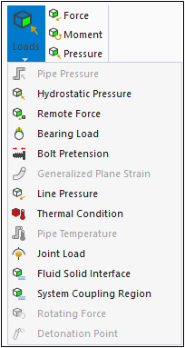
Click the desired drop-down menu from the Context tab and select your boundary condition type.
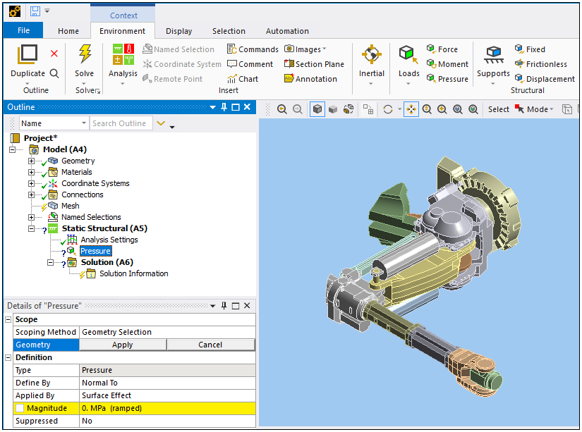
Select the desired geometry or geometries (by pressing and holding [Ctrl]) on your model and then clicking the button. Perform any additional required entries.
In the example shown here, a Pressure was applied to a face. The Magnitude entry is undefined.

Or you can first select geometries and then apply boundary conditions:
Highlight the Environment object
Pick your geometry.
Apply your boundary condition by:
Making a selection from the Environment Context tab.

Or...
Selecting the Environment object, right-clicking, select Insert and then your desired boundary condition.

Or...
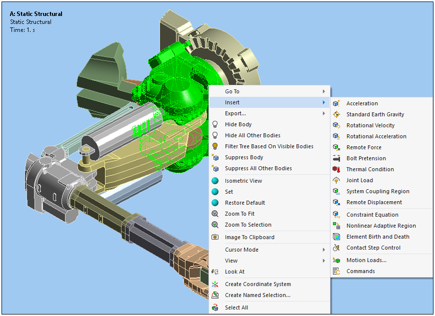
Right–clicking in the Geometry window, selecting Insert, and then selecting your desired boundary condition.

Again, additional entries are typically required. For example, you may need to enter a Magnitude for the boundary condition, specify a Coordinate System, and/or define a Direction.


