


This boundary condition applies a pretension load, typically to model a bolt under pretension. This boundary condition can be scoped to any of the following:
|
|
This page includes the following sections:
| Analysis Types |
| Dimensional Types |
| Geometry Types |
| Topology Selection Options |
| Define By Options |
| Magnitude Options |
| Applying a Bolt Pretension Boundary Condition |
| Details Pane Properties |
| API Reference |
Analysis Types
A Bolt Pretension load is applicable to pure structural or thermal-stress analyses. It is supported for the following analysis types:
Dimensional Types
The supported dimensional types for the Bolt Pretension boundary condition include:
3D Simulation
2D Simulation: Supported for Body scoping only.
Be sure that a sufficiently fine mesh exists on a face or body that contains a Bolt Pretension boundary condition so that the mesh can be correctly partitioned along the axial direction (that is, at least two elements long).
Geometry Types
The supported geometry types for Bolt Pretension include:
Solid
Surface/Shell
Wire Body/Line Body/Beam: Supported for Line Body only.
Topology Selection Options
The supported topology selection options for the Bolt Pretension boundary condition include:
Body
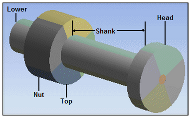
Body scoping of a Bolt Pretension load can be to more than one body. In this case all the scoped bodies are cut. There is still only a single Bolt Pretension load created but this feature allows you to apply a bolt load to a bolt that has been cut into several bodies. This feature is illustrated in the following figure.
Use caution when defining bolt loads by bodies and a coordinate system because the entire body is sliced along the local cutting plane.
Face
If you try to apply a pre-load on the same face more than once, all definitions except the first one are ignored.
Face selection simulates one Bolt Pretension load through multiple split faces of a body. When simulating Bolt Pretension using Face selection scoping on a body with multiple split faces, you need to scope/apply only one the Bolt Pretension boundary condition to only one split face. Even though you select only part of the cylinder body, the Bolt Pretension boundary condition slices through the whole cylinder body.
Care should be used when applying a Bolt Pretension boundary condition to a cylindrical face that has bonded contact. There is a possibility that if you apply a Bolt Pretension boundary condition to a cylinder that had a bonded contact region, the bonded contact will block the ability of the Bolt Pretension to deform properly.
The Bolt Pretension boundary condition should be applied to cylindrical faces that contain the model volume (that is, do not try to apply the Bolt Pretension load to a hole).
The Bolt Pretension boundary condition does not support scoping to a Virtual Cell (merged faces).
Edge. An option for applying the boundary condition to a line body is to apply it to a single straight edge on the body. The direction of the boundary condition is inferred from the direction of the edge.
For this scoping type, the Bolt Pretension boundary condition slices through the elements that fall on the cutting plane and within a circular area centered at the origin of the specified coordinate system. The radius of the circular area is the maximum value of the distances calculated from the origin of the specified coordinate system to each of the scoped element faces. Therefore, this scoping requires coordinates. A Coordinate System Behavior displays automatically for this scoping method and defaults to the setting . A option is also available to enable you to select a user-defined coordinate. Element
You can scope a Bolt Pretension load to one or more bodies. When you select multiple bodies, all the bodies are cut along the local cutting plane. There is still only a single Bolt Pretension load created but this feature enables you to apply one bolt load to a bolt that has been cut into several bodies. Beam Connection. Note the following when using a beam connection with a pretension load:
When you select as your Scoping Method, a corresponding Beam Connection property displays in the Details pane. This property provides a drop-down list of available beam connections. In addition, when you specify as your Scoping Method, the Coordinate System property is unavailable in the Details.
Tip: You can drag and drop Beam Connection objects onto an Environment to automatically created Bolt Pretension objects.
A Bolt Pretension probe can be scoped to a Bolt Pretension defined using the Beam Connection option but a Bolt Tool cannot.
Important: For this beam connection scoping scenario, the solver creates two beam elements. As a result, beam probes do not support the Result Selection property options (At I/J) and (At I/J). If selected, the application issues a warning message indicating that the results reported at location J are midspan values.
. You can use this option when you have imported a pretension load through the External Model system.
Limitation: This scoping option does not support the setting for the Formulation property.
Define By Options
The supported Define By options for the Bolt Pretension boundary condition include:
. Applies a force as a preload. A Preload field is displayed where you enter the value of the load in force units.
. Applies a length as a pre-adjustment (for example, to model x number of threads). A Preadjustment property displays when is selected. Enter the value of the adjustment in length units. It applies the Preadjustment from the solved deformation value of the previous step to the specified value of the current step.
Lock. Fixes all displacements. You can set this state for any step except the first step.
Open. Use this option to leave the Bolt Pretension load open so that the load has no effect on the applied step, effectively suppressing the load for the step. Note that in order to avoid convergence issues from having under-constrained conditions, a small load (0.01% of the maximum load across the steps) is applied. You can set this state for any step.
. Applies a length as an incremental adjustment. An field is displayed where you enter the value of the in length units. When applied, the specified value gets added to the solved deformation value from the previous step. You can choose this option for any step except the first step.
Note: If a solution restart is performed from a substep of a load step that has an specified, the increment value gets added to the solved deformation value at the beginning of the selected restart sub-step.
Magnitude Options
Bolt Pretension is defined by constant loading data only.
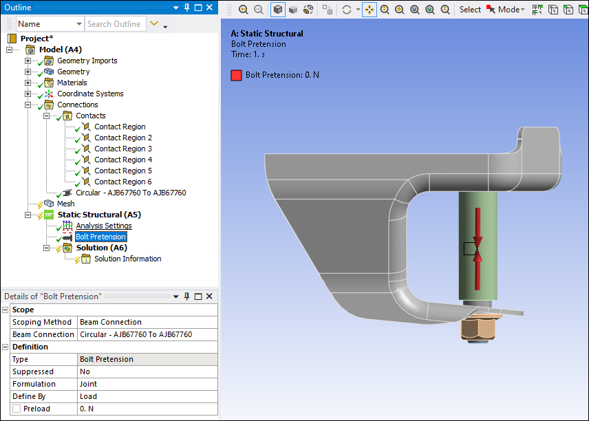
Applying a Bolt Pretension Boundary Condition
To apply a Bolt Pretension:
On the Environment Context tab, open the Loads drop-down menu and select Bolt Pretension. Alternatively, right-click the Environment object or within the Geometry window, and select Insert > Bolt Pretension.
Define the Scoping Method as either Geometry Selection, Named Selection, Beam Connection, or Pretension Section and then specify the desired cylindrical body/bodies, mesh entity, connection, or section.
Coordinate System definition can be performed based on your geometric or mesh entity scoping:
The Coordinate System Behavior property displays when Faces, Edges, or Element Faces are specified through the scoping. The options for this property include , where the application defines the coordinates, or , which displays a Coordinate System property that you use to select a user-defined coordinate system.
The Coordinate System property displays when solid bodies or elements are specified through the scoping. This option enables you to select a user-defined coordinate system.
Note: When the scoping requires you to specify the Coordinate System, the application of the boundary condition is at the origin and along the z-axis (3D) or x-axis (2D) of the coordinate system. You can place the coordinate system anywhere in the body and reorient the required axis.
Specify the Formulation property as needed. This property is only available for 3D analyses. If the bolt specified with pretension is likely to undergo large rotation, set this property to to instruct the application to use element MPC184. This element updates its orientation axis as the bolt undergoes rotation and helps the solution converge. For the use of the Formulation type, review the Considerations and Restrictions for Preload Sections topic in the Defining Preload in a Joint Fastener Undergoing Large Rotation section of the Mechanical APDL Basic Analysis Guide for limitations and restrictions on its use.
Using the Define By property, specify how the boundary condition is defined: by Load, Adjustment, or Open.
Specify a Preload or Preadjustment value as needed.
If the Scoping Method is set to either Geometry Selection or Named Selection, you can specify the Solve Behavior and Tolerance properties.
Details Pane Properties
The selections available in the Details pane are described below.
| Category | Properties/Descriptions |
|---|---|
|
Scope |
Scoping Method: The options for this property include Geometry Selection (default), Named Selections, Beam Connection, and . Geometry: This property displays when the Scoping Method is set to Geometry Selection. In this case, use selections filter to pick geometry or mesh entities, click in the Geometry field, then click Apply. Named Selection: This property displays when the Scoping Method is set to Named Selection. Select a desired Named Selection from the drop-down menu. : This property displays when the Scoping Method is set to . It enables you to scope the pretension load to a Beam Connection available from the drop-down menu of user-defined beam connections. : This property displays when the Scoping Method is set to . It enables you to scope the load using a pretension load imported through the External Model system. Coordinate System (Body/Element scoping only): This property provides a drop-down list of selectable coordinate systems. Only coordinate systems specified in the XY Plane are supported. The is the default setting. This property is not available for Beam Connection scoping. Coordinate System Behavior: This option is only visible when your scoping is made with a Face, Edge, or Element Face. Options include and . When you select the option, an associated Coordinate System property displays with the default setting of . You can specify a new user-defined Coordinate System as desired. Important: For the option, Element Face selections must be cylindrical for the application to properly calculate the corresponding Coordinate System (along Z Axis). If you do not use a cylindrical scoping, you need to set the property to and specify the coordinate system. |
|
Definition |
Type: Read-only field that displays boundary condition type - Bolt Pretension. Suppressed: Options include (default) and . Formulation: This property is only available for 3D analyses. Options include (default), , and . If a bolt specified with pretension is likely to undergo large rotation, set this property to to instruct the application to use element MPC184. This element updates its orientation axis as the bolt undergoes rotation and helps the solution converge. The option indicates that little to no rotation will take place and is the option used for the default. Define By: The options for this property include:
Preload: Visible when the Define By property is set to Load. Preadjustment: Visible when the Define By property is set to Adjustment. Increment: Visible when the Define By property is set to Increment. |
|
Advanced |
Solve Behavior: This property (and category) displays when the Scoping Method property is set to either Geometry Selection (default) or Named Selections. This property enables you to specify how the application solves your Bolt Pretension boundary condition. The options for this property include:
Tolerance: This property displays when the Scoping Method property is set to either Geometry Selection (default) or Named Selections. Using this property, you can specify a tolerance that enables the application to identify nodes that occur precisely at or that are slightly below the cutting plane. This entry essentially enables you to shift the plane by a desired value. If set to 0, the application automatically calculates a default value. |
The following example shows a Bolt Pretension load as a preload force and as a pre-adjustment length:
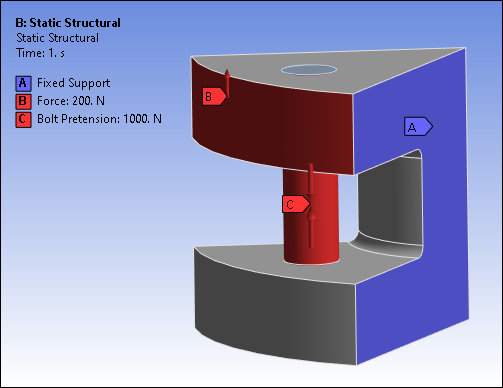 |
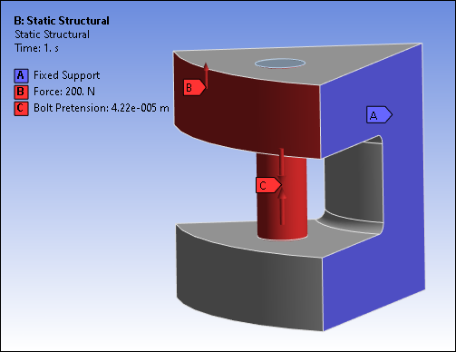 |
The following animation shows total deformation:
The following demo is presented as an animated GIF. View online if you are reading the PDF version of the help. Interface names and other components shown in the demo may differ from those in the released product.
API Reference
For specific scripting information, see the Bolt Pretension section of the ACT API Reference Guide.