


The Element Birth and Death object enables you to activate and/or deactivate the element status for a specific load step in your analysis.
When you deactivate an element or elements (Death), the solver does not remove elements. Instead, the solver deactivates the elements by multiplying their stiffness (or conductivity, or other analogous quantity) by a reduction factor so severe that the application renders the elements inactive.
Any load associated with deactivated elements:
Zero-out of the loading vector. This includes mass, damping, specific heat, and other such effects.
Does not include the mass and energy of deactivated elements in the summations over the model.
The application also sets strains to zero as soon as that element is deactivated.
Likewise, for activated elements (Alive), the application does not add the elements to the model. They are simply reactivated. You need to first deactivate an element in order to reactivate the element for the desired load step.
When you reactivate elements, stiffness, mass, element loads, etc., return to their original values. The application reactivates elements with no record of strain history (heat storage, etc.); the application considers reactivated elements to be generally strain-free. However, thermal strains are computed for newly-activated elements based on the current step temperature and the reference temperature. Therefore, newborn elements with thermal loads may not be stress-free as intended.
This feature is useful for analyzing excavation (as in mining and tunneling), staged construction (as in shored bridge erection), sequential assembly (as in fabrication of layered computer chips), and many other applications in which you can easily identify activated or deactivated elements by their known locations.
Element Birth and Death Requirements
Review the following guidelines when applying the Element Birth and Death object:
You cannot apply Constraint Equations to inactive DOFs. Inactive DOFs occur when a node has no active (Alive) elements attached to it.
You can model stress-relieving operations (such as annealing) by deactivating and then reactivating elements.
During nonlinear analyses, do not deactivate or reactivate elements in such a way as to create singularities (such as sharp re-entrant corners in a structural analysis) or sudden large changes in stiffness. Convergence difficulties may result.
The setting for the Newton-Raphson Option property (Analysis Settings> Nonlinear Controls ) automatically specifies the setting if a Dead element status is detected.
The Nonlinear Solution read-only property (Analysis Settings > Analysis Data Management) is automatically set to the setting.
In order to obtain a good result, Ansys recommends that you set the Large Deflection property (Analysis Settings> Solver Controls) to .
If you deactivate a Contact Region using the Contact Step Control feature or if you deactivate the underlying elements of a Contact Region using the Element Birth and Death feature, the application changes the status of the contact pair to far field contact (open and not near contact). This includes bonded contact. To reestablish the pre-death contact status when reactivating the Contact Region, you may need to deactivate both the Contact Region and their underlying elements.
If an element in a Static Structural analysis is killed during the first load step and then activated in the subsequent load step, any downstream Linear Perturbation analyses restarted from the activated load step will activate the element during the first phase of the analysis. However, if an element in a Static Structural analysis is active during the first load step and then deactivated in the subsequent load step, any downstream Linear Perturbation analyses restarted from the deactivated load step will deactivate the element during the first phase of the analysis. For additional information, see the First Phase of the Linear Perturbation Analysis in the Mechanical APDL Structural Analysis Guide.
For additional information, see the Element Birth and Death topic in the Mechanical APDL Advanced Analysis Guide.
This page includes the following sections:
| Analysis Types |
| Dimensional Types |
| Geometry Types |
| Topology Selection Options |
| Applying an Element Birth and Death Boundary Condition |
| Details Pane Properties |
| Mechanical APDL References and Notes |
| API Reference |
Analysis Types
Element Birth and Death is available for the following analysis types:
Dimensional Types
The supported dimensional types for the Element Birth and Death boundary condition include:
3D Simulation
2D Simulation
Geometry Types
The supported geometry types for the Element Birth and Death boundary condition include:
Solid
Surface/Shell
Wire Body/Line Body/Beam
Topology Selection Options
The supported topology selection options for Element Birth and Death include:
Body
Elements
Applying an Element Birth and Death Boundary Condition
To apply an Element Birth and Death condition:
On the Environment Context tab, click Conditions>Element Birth and Death. Alternatively, right-click the Environment tree object or within the Geometry window and select Insert>Element Birth and Death.
Define your Scoping Method and select geometry.
Define the desired number of steps in the Step Controls category of the Analysis Settings.
Select a desired step in the Current Step property of the Element Birth and Death object.
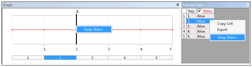
Specify the Status of each load step as desired, or . The default setting for each step is . The Graph and Tabular Data windows each provide the right-click option . This option also changes the Status of a load step.
Details Pane Properties
The selections available in the Details pane are described below.
| Category | Properties/Options/Descriptions |
|---|---|
| Scope |
Scoping Method: Options include:
|
| Definition |
Type: Read-only field that describes the object - Element Birth and Death. Suppressed: Include ( - default) or exclude () the condition. |
| Step Controls |
Current Step: This property displays the currently selected Step. This step is also highlighted in the Graph window. Status. The options for this property include:
|
Mechanical APDL References and Notes
The following Mechanical APDL commands and considerations are applicable for this condition.
In order to create the Element Birth and Death component, the application uses the CM command for body-based scoping and the CMBLOCK command for element-based scoping.
When the application completes the creation of the Element Birth and Death components, it issues the ALLSEL ,ALL command.
The application issues the EKILL command when the is changed from to or at the first step.
The application issues the EALIVE command when the is changed from to .
API Reference
For specific scripting information, see the Element Birth and Death section of the ACT API Reference Guide.