You can detonate an explosive by various methods of delivering energy to it. However whether an explosive is dropped, thermally irradiated, or shocked, either mechanically or through a shock from an initiator (of a more sensitive explosive), initiation of an explosive always goes through a stage in which a shock wave is an important feature.
It is assumed that, on initiation, a detonation wave travels away from the initiation point with constant detonation velocity, being refracted around any inert obstacles in the explosive without moving the obstacle, maintaining a constant detonation velocity in the refracted zone and detonating each particle of explosive on arrival at that particle.
For information on an alternative method for initiating the detonation process, see Burn on Compression.
Analysis Types
Detonation Point is available for Explicit Dynamics and LS-DYNA analyses.
Common Characteristics
This section describes the characteristics of the boundary condition, including the application requirements, support limitations, and loading definitions and values.
Dimensional Types
3D Simulation: Supported.
2D Simulation: Supported.
Note: Detonation Points are slightly different in LS-DYNA.
Boundary Condition Application
Click the drop-down menu from the Context tab and select Detonation Point. Or, right-click the Environment tree object or the Geometry window and select > .
Specify Location.
Multiple detonation points can be added to an analysis. The location of the selected detonation point and the detonation time are displayed in the annotation on the model.
Details View Properties
The selections available in the Details view are described below.
| Category | Fields/Options/Description |
|---|---|
| Definition |
Burn Instantaneously: When set to , results in initiation of detonation for all elements with an explosive material at the start of the solve. : User can enter the time for initiation of detonation. [Only visible if Burn Instantaneously is set to .] Suppressed - Include ( - default) or exclude () the boundary condition. |
| Location |
Enter detonation point coordinates:
Location: User can interactively select detonation location using the vertex/edge/face selection tools:
|
Theory
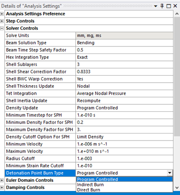
Detonation paths are computed by finding either a direct path through explosive regions, or by an indirect method that follows straight line segments connecting centers of cells containing explosives. The path type can be defined using the Detonation Point Burn Type field in the Analysis Settings.
Note: For 3D analyses the default (Program Controlled) setting uses indirect path computation, while for 2D analyses, the default is direct path computation.
The correct detonation paths will automatically be computed around wave-shapers, obstacles, corners, etc.
Detonation points must lie within the grid. Paths cannot be computed through multiple Parts. If a detonation point is placed in one Part, the detonation from this point cannot propagate to another Part. If this is required, you must place one or more detonation points in the second Part with the appropriate initiation times set to achieve the required detonation.
The following illustration outlines the detonation process:
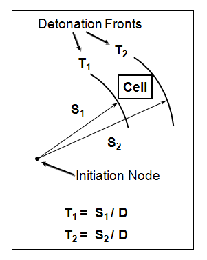
Detonation is initiated at a node or plane (user defined)
Detonation front propagates at the Detonation Velocity, D
Cell begins to burn at time T1
Burning is complete at time T2
Chemical energy is released linearly from T1 to T2; burn fraction increases from 0.0 to 1.0 over this time
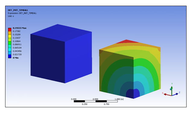
The result DET_INIT_TIME can be used to view the initiation times of the explosive material. For example, in the image below, the body on the left side has a detonation point with instantaneous burn defined, and so the entire material has a detonation initiation time of 1x10⁻⁶ ms. The second body has a detonation point defined in the lower X, lower Y, lower Z corner, and the detonation time can be seen to vary from 0 ms (in other words, instantaneous detonation) to a value of 0.19555 ms in the corner of the body furthest away from the detonation point. Once detonation is initiated in an element, a value of zero is shown for DET_INIT_TIME.
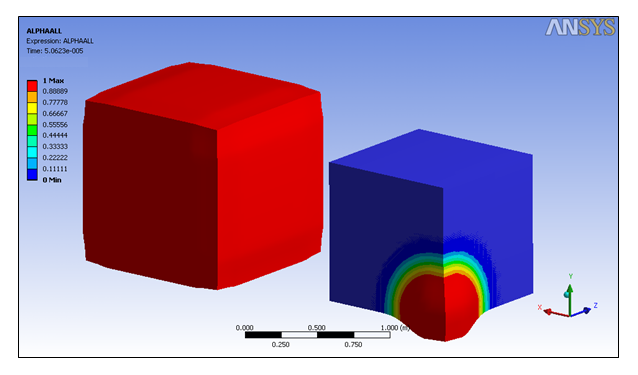
The result ALPHA can be used to view the progress of the detonation wave through the material. This corresponds to the burn fraction, which will be a value between zero (no detonation) and one (detonation complete). For the same example, looking at values of alpha at a later stage in the calculation, the detonation wave can clearly be seen in the body on the right as the spherical band of contours showing the value of alpha changing from zero to one. The body on the left has a value of one for the entire body, as it detonated instantaneously.