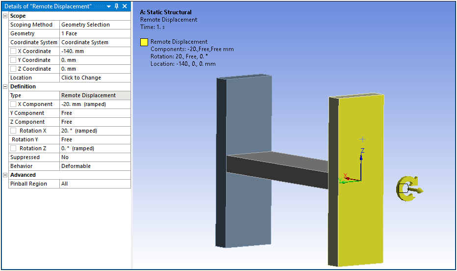
The Remote Displacement boundary condition enables you to apply both displacements and rotations at an arbitrary remote location in space. You specify the origin of the remote location under Scope category in the Details by picking or by entering the XYZ coordinates directly. The default location of the origin is at the centroid of the model. You specify the displacement and rotation under Definition.
A Remote Displacement is classified as a remote boundary condition. For a listing of all remote boundary conditions and their characteristics, see the Remote Boundary Conditions section.
This page includes the following sections:
Analysis Types
Remote Displacement is available for the following analysis types:
[a] For a Modal analysis, only zero magnitude Remote Displacement values are valid. These function as supports. If non-zero magnitude remote displacements are needed for a Pre-Stress Modal analysis, apply the Remote Displacement in the static structural environment.
Dimensional Types
The supported dimensional types for the Remote Displacement boundary condition include:
3D Simulation
2D Simulation
Geometry Types
The supported geometry types for the Remote Displacement boundary condition include:
Solid
Surface/Shell
Wire Body/Line Body/Beam
Topology Selection Options
The supported topology selection options for Remote Displacement include:
Face
Edge
Vertex. This boundary condition cannot be applied to a vertex scoped to an end release.
Nodes
Element Face
- Applying Remote Loads to a Straight Edge
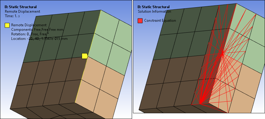
If you apply a remote load to a straight edge (with colinear nodes) of a deformable surface body or a solid body, the application applies the load to the edge as well as the neighboring nodes of the element faces of the deformable surface body or the solid body, respectively. This transfers the rotations of the pilot node (of the Remote Point) to the surface or solid body.
Exception: If you scope a remote load to a deformable beam, the application internally changes the setting of the Behavior property to and prompts you with a warning.
The following example shows how the application applies a Remote Displacement, scoped to a straight edge, to the neighboring element face nodes. In this example, the imbalance of constraint equations created on the blocks might result in unwanted non-zero moment reactions. You can minimize this by using either a lower order mesh or a coarser higher order mesh. For more information, see the Surface-Based Constraints section of the Mechanical APDL Contact Technology Guide.
Define By Options
The supported Define By options for the Remote Displacement boundary condition include:
X Component
Y Component
Z Component
X Rotation
Y Rotation
Z Rotation
Magnitude Options
The supported Magnitude options for Remote Displacement include the following:
(Time Varying)
Tabular (Step Varying): Supported for Static Structural analysis only.
(Time Varying)
Applying a Remote Displacement Boundary Condition
To apply a Remote Displacement:
On the Environment Context tab, click Supports>Remote Displacement. Alternatively, right-click the Environment tree object or in the Geometry window and select Insert>Remote Displacement.
Define the Scoping Method.
Specify the origin of the remote location or enter the XYZ coordinates. The default location is at the centroid of the geometry.
As needed, set the Rev Dir for Inv Steps property to . See the description below for requirements.
Specify the translational and rotational displacement components.
Note: Because a Remote Displacement is a remote boundary condition, it can make use of remote points that were either specifically defined or created internally by the application. As a visual check, you can display connection lines between your scoping and the remote point by selecting the Remote Point Connections option of the Style group (Display tab).
Details Properties
The selections available in the Details are described below.
| Category | Property/Options/Description |
|---|---|
| Scope |
Scoping Method: Options include:
Coordinate System: Drop-down list of available coordinate systems. is the default. Z Coordinate Y Coordinate X Coordinate Note: Selection of a Coordinate System rotated out of the global Cartesian X-Y plane is not supported in a 2D analysis. Location: The location of a Remote Displacement can be defined in the Global Coordinate System or in a local Cartesian coordinate system. It is by default at the centroid of selected geometry. |
| Definition |
Type: Read-only field that describes the object - Remote Displacement. X Component: Defines distance (+/-) in the X direction. Y Component: Defines distance (+/-) in the Y direction. Z Component: Defines distance (+/-) in the Z direction. X Rotation: Defines rotational distance (+/-) in the X direction. Y Rotation: Defines rotational distance (+/-) in the Y direction. Z Rotation: Defines rotational distance (+/-) in the Z direction. Rev Dir for Inv Steps: This property is only available when the following Advanced Analysis Settings properties are defined:
Options include (default) and . Setting this property to inverts the direction of your specified Remote Displacement and is displayed by the change in direction of the displacement annotation in the Geometry window. Suppressed: Include ( - default) or exclude () the boundary condition. Behavior: , , , or . The option specifies a connection from the remote load to the model using linear massless beam elements. If the Scope Method property is set to , the boundary condition will then assume the Behavior defined in the referenced Remote Point as well as other related properties. Material: This property is available when the Behavior property is set to . Select a material to define material properties for the beams used in the connection. Density is excluded from the material definition. Radius: This property is available when the Behavior property is set to . Specify a radius to define the cross section dimension of the circular beam used for the connection. |
| Advanced | Pinball Region: Specify the radius of the sphere (length unit). The displacement is applied to the elements that are within the pinball region. |
API Reference
For specific scripting information, see the Remote Displacement section of the ACT API Reference Guide.
Example Applications
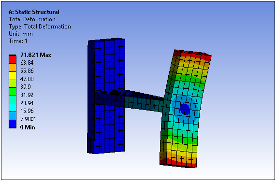
A common application is to apply a rotation on a model at a local coordinate system. An example is shown below along with a plot of the resulting Total Deformation.
Total Deformation Result Example