


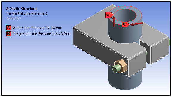
For 3D simulations, a Line Pressure load applies a distributed force using force density loading in units of force per length. You can define force density as a vector, an axial component, or tangentially. Tangential loads can be applied to one edge only whereas vector and component loads and can be applied to one or more edges.
If a pressurized edge enlarges due to a change in CAD parameters, the total load applied to the edge increases, but the pressure (force per unit length) remains constant.
This page includes the following sections:
Analysis Types
Line Pressure is available for the following analysis types:
Dimensional Types
The supported dimensional types for the Line Pressure boundary condition include:
3D Simulation
Geometry Types
The supported geometry types for the Line Pressure boundary condition include:
Solid
Surface/Shell
Wire Body/Line Body/Beam
Topology Selection Options
The supported topology selection options for Line Pressure include:
Edge
Define By Options
The supported Define By options for the Line Pressure boundary condition include:
The vector load definition displays in the Annotation legend with the label Components. The Magnitude and Direction entries, in any combination or sequence, define these displayed values. These are the values sent to the solver.
: Supported (scoped to one edge only).
Magnitude Options
The supported Magnitude options for Line Pressure include the following:
Constant. This is the only option supported for Explicit Dynamics.
Tabular (Time Varying)
Tabular (Step Varying): Supported for Static Structural analysis only.
Tabular (Spatially Varying): Supported for Tangential loading only.
Function (Time Varying)
Function (Spatially Varying): Supported for Tangential loading only.
Applying a Line Pressure Boundary Condition
To apply a Line Pressure:
On the Environment Context tab, open the Loads drop-down menu and select Line Pressure. Alternatively, right-click the Environment tree object or in the Geometry window and select Insert>Line Pressure.
Define the Scoping Method as either Geometry Selection or Named Selection and then specify the geometry.
Select the method used to define the Line Pressure: Vector (default), Tangential, or Components.
Define the Magnitude, Coordinate System, and/or Direction of the Line Pressure based on the above selections.
Note: The Direction property is not associative and does not remain joined to the entity(s) selected for its specification. Therefore, this direction is not affected by geometry updates, part transformation, or the Configure tool (for joints).
For Harmonic analyses, specify a Phase Angle as needed.
Details Pane Properties
The selections available in the Details pane are described below.
| Category | Property/Options/Description |
|---|---|
| Scope | Scoping Method: Options include:
|
| Definition |
Type: Read-only field that displays boundary condition type - Line Pressure. Define By, options include:
Phase Angle (Harmonic Analysis only). Suppressed: Include ( - default) or exclude () the boundary condition. |
Mechanical APDL References and Notes
The following Mechanical APDL commands, element types, and considerations are applicable for this boundary condition.
API Reference
For specific scripting information, see the Line Pressure section of the ACT API Reference Guide.