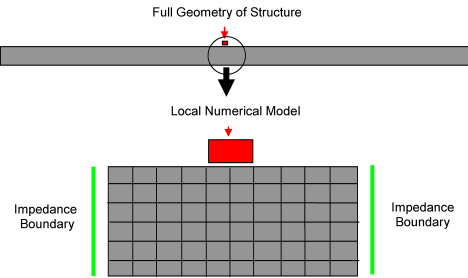
Impedance Boundary is available for an Explicit Dynamics analysis only. It is not available for LS-DYNA.
You can use the impedance boundary condition to transmit waves through cell faces. The boundary condition predicts the pressure P in the dummy cell from the impedance, particle velocity, and a reference pressure (P0). Only the perpendicular component is transmitted, as the pressure is spherical. Therefore, the Impedance boundary condition is only approximate, and should be placed as far as possible from region of interest.
Theory
In order to economize on problem size, it is sometimes advantageous for problems which have only outward traveling solutions (e.g. an expanding high pressure source) to limit the size of the grid by a boundary condition which allows outward traveling waves to pass through it without reflecting energy back into the computational grid.

In practice it proves impossible to include a simple boundary condition which is accurate for all wave strengths but the algorithm used here give a reasonable approximation over a wide spectrum. However it should always be borne in mind that the condition is only approximate and some reflected wave, however small, will be created and care must be taken that such a wave does not have a significant effect on the later solution. Note that the following analysis deals only with the normal component of velocity of the wave and the velocity component parallel to the boundary is assumed to be unaffected by the boundary.
For a one-dimensional wave traveling in the direction of increasing x, the conditions on the rearward facing characteristic are
(5–1) |
where ρc is the acoustic impedance (ρ is the local density and c is the local sound speed) and dp and du are the changes of pressure and velocity normal to the wave along the characteristic. Since it is assumed that no wave energy is being propagated back in the direction of decreasing x the error in applying the above condition on a non-characteristic direction is in general small and it is applied on the transmitting boundary in the form
(5–2) |
where:
uN is the component of mean velocity normal to the boundary
[ρc]boundary is the assumed Material Impedance for the boundary
pref is the user defined reference pressure
uref is the user defined reference velocity at the boundary
For an initially stationary structure at zero pressure, the reference values (pref and uref) are normally set to zero. In this case we have
(5–3) |
which is exact for a plane elastic longitudinal wave propagating in an infinite elastic medium.
Note: The default Material Impedance (Program Controlled) is zero. In this case the impedance at the boundary is taken to be the impedance at time t of the element to which the boundary is applied. This represents the case of perfect transmission of plane normal elastic waves.
Common Characteristics
The following section outlines the common boundary condition characteristics that include application requirements of the boundary condition, support limitations, as well as loading definitions and values.
Dimensional Types
3D Simulation: Supported.
2D Simulation: Supported.
Geometry Types: Geometry types supported for the Impedance Boundary boundary condition include:
Solid: Supported.
Surface/Shell: Supported.
Wire Body/Line Body/Beam: Supported.
Topology: The following topology selection options are supported for Impedance Boundary.
Body: Not Supported.
Face: Supported.
Edge: Not Supported.
Vertex: Not Supported.
Nodes: Not Supported.
Loading Data Definition: Enter loading data using one of the following options.
Boundary Condition Application
To apply an Impedance Boundary:
On the Environment Context tab: click Supports and select . Or, right-click the Environment tree object or the Geometry window and select Insert>Impedance Boundary.
Define the Scoping Method.
Details View Properties
The selections available in the Details view are described below.
| Category | Fields/Options/Description |
|---|---|
| Scope |
Scoping Method: Options include:
|
| Definition |
Type: Read-only field set to Impedance Boundary. Material Impedance: Program Controlled or input value. Reference Velocity: Program Controlled or input value. Reference Pressure: Program Controlled or input value. Suppressed: Include ( - default) or exclude () the boundary condition. |


