


SECDATA
SECDATA, VAL1, VAL2, VAL3, VAL4, VAL5, VAL6, VAL7, VAL8, VAL9, VAL10, VAL11, VAL12
Describes the geometry of a section.
-
VAL1,VAL2,VAL3, . . . ,VAL12 Values, such as thickness or the length of a side or the numbers of cells along the width, that describe the geometry of a section. The terms
VAL1,VAL2, etc. are specialized for each type of cross-section.
Notes
The SECDATA command defines the data describing the geometry of a section. The command is divided into these section types: Beams, Contact, General Axisymmetric, Joints, Links, Pipes, Pretension, Reinforcing, Shells, Supports, and Taper.
The data input on the SECDATA command is interpreted based on the most recently issued SECTYPE command. The data required is determined by the section type and subtype, and is different for each one.

Beams
Type: BEAM
Beam sections are referenced by BEAM188 and BEAM189 elements. Not all SECOFFSET location values are valid for each subtype.
|
Type: BEAM, Subtype: RECT
|
Type: BEAM, Subtype: QUAD
Degeneration to triangle is permitted by specifying the same coordinates for cells along an edge. | ||||||||||||||||||||||||
|
Type: BEAM, Subtype: CSOLID
|
Type: BEAM, Subtype: CTUBE
This subtype is similar to type PIPE. However, elements using PIPE account for internal or external pressures, whereas elements using CTUBE do not. | ||||||||||||||||||||||||
|
Type: BEAM, Subtype: CHAN
|
Type: BEAM, Subtype: I
| ||||||||||||||||||||||||
|
Type: BEAM, Subtype: Z
|
Type: BEAM, Subtype: L
If | ||||||||||||||||||||||||
|
Type: BEAM, Subtype: T
If |
Type: BEAM, Subtype: HATS
| ||||||||||||||||||||||||
|
Type: BEAM, Subtype: HREC
|
Type: BEAM, Subtype: ASEC
SECPLOT cannot display an ASEC plot. | ||||||||||||||||||||||||
|
Type: BEAM, Subtype: MESH
|


CONTACT
Type: CONTACT
Geometry Correction — Contact sections for geometry correction (Subtype = CIRCLE,
SPHERE, or CYLINDER) are referenced by the following elements: TARGE169, TARGE170,
CONTA172, and CONTA174. This
geometry correction applies to cases where the original meshes of contact elements or target
elements are located on a portion of a circular, spherical, or revolute surface.
Type: CONTACT, Subtype: CIRCLE
Data to provide in the value fields for Subtype =
CIRCLE: |
X0, Y0 (circle center location in Global
Cartesian coordinates - XY plane) |
Type: CONTACT, Subtype: SPHERE
Data to provide in the value fields for Subtype =
SPHERE: |
X0, Y0, Z0
(sphere center location in Global Cartesian coordinates) |
Type: CONTACT, Subtype: CYLINDER
Data to provide in the value fields for Subtype =
CYLINDER: |
X1, Y1, Z1,
X2, Y2, Z2
(two ends of cylindrical axis in Global Cartesian coordinates) |
User-Defined Contact Surface Normal — The contact section for a user-defined contact surface normal
(Subtype = NORMAL) is referenced by the following elements: CONTA172, CONTA174,
and CONTA175. This geometry correction is used to define a
shift direction for interference
fit solutions.
Type: CONTACT, Subtype: NORMAL
Data to provide in the value fields for Subtype =
NORMAL: |
CSYS, NX, NY,
NZ
|
| where: |
CSYS = Local coordinate system number (defaults to global
Cartesian). |
NX, NY, NZ =
Direction cosines with respect to CSYS.
|
Radius values associated with contact or target elements — The radius contact section (Subtype = RADIUS) is referenced by
contact or target elements in a general contact definition under the following circumstances:
Equivalent 3D contact radius for beam-to-beam contact - The contact section for a user-defined equivalent contact radius (
Subtype= RADIUS) is referenced by the element type CONTA177 within a general contact definition. 3D beam-to-beam contact (or edge-to-edge contact) modeled by this line contact element assumes that its surface is a cylindrical surface.Radius (or radii) of rigid target segments - The contact section for rigid target segment radii is referenced by target elements TARGE169 (circle segment type) and TARGE170 (line, parabola, cylinder, sphere, or cone segment type) in a general contact definition.
Type: CONTACT, Subtype: RADIUS
Data to provide in the value fields for Subtype = RADIUS if
the section is used as an equivalent contact radius for 3D beam-to-beam contact: |
VAL1 = Equivalent radius - outer radius |
VAL2 = Equivalent radius - inner radius (internal beam-to-beam
contact) |
VAL3: Set to 1 for internal beam-to-beam contact. Defaults to
external beam-to-beam contact. |
Data to provide in the value fields for Subtype = RADIUS if
the section is used for 2D or 3D rigid target segments: |
VAL1 = First radius of the target segment (used for circle, line,
parabola, cylinder, sphere, and cone segment types) |
VAL2 = Second radius of the target segment (used only for the cone
segment type) |
Simplified Bolt Thread Modeling — The contact section for bolt-thread modeling (Subtype = BOLT)
is referenced by the following elements: CONTA172, CONTA174, and
CONTA175. It applies to cases where the original meshes of
contact elements are located on a portion of a bolt-thread surface. This feature allows you to
include the behavior of bolt threads without having to add the geometric detail of the threads.
Calculations are performed internally to approximate the behavior of the bolt-thread
connections.
Type: CONTACT, Subtype: BOLT
Data to provide in the value fields for Subtype =
BOLT: |
Dm
, P, ALPHA,
N, X1, Y1,
Z1, X2, Y2,
Z2
|
| where: |
Dm
= Pitch diameter, dm. |
P = Pitch distance, p. |
ALPHA = Half-thread angle, α (defaults to 30 degrees). |
N = Number of starts (defaults to 1). |
X1, Y1, Z1,
X2, Y2, Z2 =
Two end points of the bolt axis in global Cartesian coordinates. |

General Axisymmetric
Type: AXIS
General axisymmetric sections are referenced by the SURF159, SOLID272, and SOLID273 elements. Use this command to locate the axisymmetric axis.
| Data to provide in the value fields: |
| Pattern 1 (two points): |
1, X1, Y1,
Z1, X2, Y2,
Z2
|
where X1, Y1,
Z1, X2, Y2,
Z2 are global Cartesian coordinates. |
| Pattern 2 (coordinate system number plus axis [1 = x, 2 = y, 3 = z] ): |
2, csys, axis
|
where csys is a Cartesian coordinate system. |
| Pattern 3 (origin plus direction): |
3, XO, YO,
ZO, xdir,
ydir, zdir
|
where XO, YO,
ZO
are global Cartesian coordinates and xdir,
ydir, and zdir are direction
cosines. |
Joints
Type: JOINT
Joint sections are referenced by MPC184 joint elements.
| Data to provide in the value fields: |
length1, length2,
length3, angle1,
angle2, angle3
|
| where: |
length1-3 = Reference lengths used in the constitutive
calculations. |
angle1-3 = Reference angles used in the constitutive
calculations. |
The following table shows the lengths and angles to be specified for different kinds of joints.
| Joint | Subtype | Reference lengths and angles |
|---|---|---|
| Revolute | REVO |
angle1 for x-axis revolute joint |
| Universal | UNIV | angle1 and angle3 |
| Slot | SLOT | length1 |
| Point-in-plane | PINP | length2 and length3, |
| Revolute Translational | PRIS | length1 |
| Cylindrical | CYLI |
length1 and angle1 for x-axis cylindrical joint |
| Planar | PLAN |
length2, length3, and angle1 for x-axis planar joint |
| Weld | WELD | (not used) |
| Orient | ORIE | (not used) |
| Spherical | SPHE | angle1, angle2, and angle3 (not used in friction calculations) |
| General | GENE | length1, length2, length3, angle1, angle2, angle3 -- Depends upon which "unconstrained" relative degrees of freedom are available. |
| Screw | SCRE | length3 and angle3 |
| Spotweld | SPWE | (not used) |
| Genb | GENB | length1, length2, length3, angle1, angle2, angle3 -- Depends upon which "unconstrained" relative degrees of freedom are available. |
The reference length and angle specifications correspond to the free relative degrees of freedom in a joint element for which constitutive calculations are performed. These values are used when stiffness and/or damping are specified for the joint elements.
If the reference lengths and angles are not specified, they are calculated from the default or starting configuration for the element.
See MPC184 or the individual joint element descriptions for more information on joint element constitutive calculations.
Links
Type: LINK
Link sections are referenced by the LINK33, LINK180, LINK228, and CABLE280 elements.
| Data to provide in the value fields: |
VAL1 = Area |
Pipes
Type: PIPE
Pipe sections are referenced by the PIPE288, PIPE289, and ELBOW290 elements.
Data to provide in the value fields: Do,Tw,Nc,Ss,Nt,Mint,Mins,Tinswhere: Do= Outside diameter of pipe. Use a constant value for a circular pipe and an array for a noncircular pipe. (Noncircular pipe sections are referenced by the ELBOW290 element only. See Defining a Noncircular Pipe in the Structural Analysis Guide.)Tw= Wall thickness. Default =Do/ 2, or “solid” pipe. ("Solid" pipe is not applicable to ELBOW290; for that element, a thickness less thanDo/ 4 is recommended.)Nc= Number of cells around the circumference (8
Nc120, where a greater value improves accuracy slightly; default = 8).
Ss= Section number of the shell representing the pipe wall. Valid with ELBOW290 only. (Total thickness of the section is scaled toTw. The program considers the innermost layer inside of the pipe to be the first layer.)Nt= Number of cells through the pipe wall. Valid values are 1 (default), 3, 5, 7, and 9. Cells are graded such that they are thinner on the inner and outer surfaces. Valid with PIPE288 and PIPE289 only.Mint= Material number of fluid inside of the pipe. The default value is 0 (no fluid). This value is used to input the density of the internal fluid. The fluid inside the pipe element is ignored unless the free surface in a global X-Y plane is added as face 3 (SFE) and is high enough to include at least one end node of the element.Mins= Material number of material external to the pipe (such as insulation or armoring). The default value is 0 (no external material). This value is used to input the density of the external material. (External material adds mass and increases hydraulic diameter, but does not add to stiffness.)Tins= Thickness of material external to the pipe, such as insulation. The default value is 0 (no external material).
The accuracy of the ovalization value (OVAL) output by ELBOW290 (Structural Elbow form only)
improves as the specified number of cells around the circumference
(N
c
) is increased.
External material (M
ins
) adds mass and increases hydraulic
diameter, but does not add to stiffness.

Pretension
Type: PRETENSION
Pretension sections are referenced by the PRETS179 element.
| Data to provide in the value fields: |
node, nx, ny,
nz
|
| where: |
node = Pretension node number. |
nx = Orientation in global Cartesian x direction. |
ny = Orientation in global Cartesian y direction. |
nz = Orientation in global Cartesian z direction. |
The following usage is typical:
| SECTYPE, 1, PRETENSION |
| SECDATA, 13184, 0.000, 0.000, 1.000 |
| SECMODIF, 1, NAME, example |
| SLOAD, 1, PL01, TINY, FORC, 100.00 , 1, 2 |
The PRETENSION section options of SECTYPE and
SECDATA are documented mainly to aid in the understanding of data written by
CDWRITE. Ansys, Inc. recommends that you generate pretension sections using
PSMESH.
Reinforcing
Type: REINF
Each SECDATA command defines the material, geometry, and orientation (if Subtype = SMEAR) of one reinforcing member (discrete fiber or smeared surface) in the section. The reinforcing section can be referenced by reinforcing elements (REINF263, REINF264, and REINF265), or MESH200 elements when used for temporarily representing reinforcing members. Only one SECDATA command is allowed per section when referenced by MESH200 elements. For more information, see Reinforcing and Direct Element Embedding in the Structural Analysis Guide.
- - - - - - - - - - - - - - - - - - - - -
Type: REINF, Subtype: DISCRETE
Defines discrete reinforcing fibers with arbitrary orientations. For the MESH input pattern, reinforcing section data is referenced by MESH200 elements. For other patterns, issue separate SECDATA commands to define each reinforcing fiber.
| Data to provide in the value fields: |
MAT, A, PATT, V1, V2, V3, V4, V5
|
MAT = Material ID for the fiber. (See
REINF264 for valid material models.) When the reinforcing section is
referenced by a MESH200 element, the default is the
MESH200 element material ID (MAT). When the
section is referenced by reinforcing elements, the material ID is required for all fibers, and
no default for this value is available. |
A = Cross-section area of the reinforcing fiber. |
PATT = Input pattern code (described below) indicating how the
location of this fiber is defined. Available input patterns are MESH (when the section is
referenced by a MESH200 element), and LAYN, EDGO, and BEAM (when the
section is referenced by a reinforcing element). |
V1, V2, V3, V4, V5 = Values to define the location of the
reinforcing fiber (depending on the PATT pattern code used), as
shown: |
PATT: MESH
Description: The locations of reinforcing fibers are defined directly via MESH200 element connectivity.
Required input: None.
PATT: LAYN
Description: The discrete reinforcing fiber is placed in the middle of a layer in a layered base element. The orientation of the fiber within the layer is adjustable via offsets with respect to a specified element edge.
Required input:
V1 (or N) -- The number of the layer in
the base element on which to apply the reinforcing fiber. The default value is 1. |
V2 (or e) -- The number to indicate the
element edge to which the offsets are measured. The default value is 1. |
V3 and V4 (or
Y1 and Y2) -- The normalized distances
from the fiber to the two ends of the specified element edge. Valid values for
Y1 and Y2 are 0.0 through 1.0. The
default value of Y1 is 0.5. The default value of
Y2 is Y1. |
When applied to 8-node or 20-node layered solid elements:


When applied to 4-node or 8-node layered shell elements:


PATT: EDGO
Description: The orientation of the discrete reinforcing fiber is similar to one of the specified element edges. The fiber orientation can be further adjusted via offsets with respect to the specified element edge.
Required input:
V1 (or O) -- The number to indicate the
element edge to which the offsets are measured. The default value is 1. |
V2 and V3 (or Y1
and Z1) -- The normalized distances from the fiber to
the first end of the specified element edge. Valid values for Y1 and
Z1 are 0.0 through 1.0. The default value for
Y1 and Z1 is 0.5. |
V4 and V5 (or
Y2 and Z2) – The normalized
distances from the fiber to the second end of the specified element edge. Value values for
Y2 and Z2 are 0.0 through 1.0. The
default value for Y2 is Y1, and the
default value for Z2 is Z1. |
If the base element is a beam or link, the program ignores values
V2throughV5and instead places the reinforcing in the center of the beam or link.
When applied to 8-node or 20-node solid elements:


When applied to tetrahedral elements:
 | |
 | |
 |
When applied to 3D shell elements:


When applied to beam or link elements:

PATT: BEAM
Description: Use this specialized input pattern for defining reinforcing in regular constant and tapered beams.
Required input:
V1 and V2 (or
Y1 and Z1) -- Y and Z offsets with
respect to the section origin in the first beam section referenced by the base beam element.
The default value for Y1 and Z1 is 0.0. |
V3 and V4 (or
Y2 and Z2) -- Y and Z offsets with
respect to the section origin in the second beam section referenced by the base beam element.
The default value for Y2 is Y1, and the
default value for Z2 is Z1. (Because
V3 and V4 values apply only to tapered
beams, the program ignores them if the base beam has a constant section.) |

- - - - - - - - - - - - - - - - - - - - -
Type: REINF, Subtype: SMEAR
Suitable for layers of reinforcing fibers with uniform cross-section area and spacing. Each SECDATA command defines the one reinforcing layer in the section. When referenced by a MESH200 element, only one SECDATA command per section is allowed. When referenced by reinforcing elements (REINF263 and REINF265), this limitation does not apply.
| Data to provide in the value fields: |
MAT, A, S, KCN, THETA, PATT, V1, V2, V3, V4, V5
|
| where: |
MAT = Material ID for layer. (See REINF263
or REINF265 for available material models.) When the section is
referenced by a MESH200 element, the default is the
MESH200 element material ID (MAT). When the
section is referenced by reinforcing elements, the material ID is required for all fibers, and
no default for this value is available. |
A = Cross-section area of a single reinforcing fiber
(or the thickness of the reinforcing layer for homogeneous reinforcing
membranes). |
S = Distance between two adjacent reinforcing fibers (ignored for
homogeneous reinforcing membranes). |
Note: If the section is used to
model the reinforcing layers with a uniaxial stress state (SECCONTROL,,,0),
the equivalent thickness h of the reinforcing layer is determined by h =
A / S, where
A is the cross-section area of a single fiber and
S is the distance between two adjacent fibers. If the section is
used to model homogeneous reinforcing membranes (SECCONTROL,,,1), the
cross-section area input A is the thickness of the reinforcing layer
and the distance input S is ignored. |
KCN = Local coordinate system reference number for this layer. (See
LOCAL for more information.) When the section is referenced by a
MESH200 element, the default KCN value is
the MESH200 element coordinate system ID (ESYS).
For the 2D smeared reinforcing element REINF263,
KCN input is not required. When KCN is
not specified, the program uses a default layer coordinate system (described in
REINF263 and REINF265). |
THETA = Angle (in degrees) of the final layer coordinate system
with respect to the default layer system or the layer system specified in the
KCN field. This value is ignored for
REINF263 when that element is embedded in 2D plane strain or plane
stress base elements. |
PATT = Input pattern code (described below) indicating how the
location of this fiber is defined. Available input patterns are MESH (when the section is
referenced by a MESH200 element), and LAYN, EDGO, and BEAM (when the
section is referenced by a reinforcing element). |
V1, V2, V3, V4, V5 = Values to define the location of the
reinforcing layer, as shown: |
PATT: MESH
Description: The locations of reinforcing fibers are defined directly via MESH200 element connectivity.
Required input: None.
PATT: LAYN
Description: The smeared reinforcing layer is placed in the middle of a layer in a layered base element.
Required input:
V1 (or n) -- The number of the layer in
the base element on which to apply the reinforcing layer. The default value is 1.
|
When applied to layered solid elements:  | |
|
When applied to 2D axisymmetric shells:  |
When applied to 3D layered shells:  |
PATT: EDGO
Description: This pattern applies only to 2D smeared reinforcing element REINF263. The smeared reinforcing layer is represented by a line in 2D. The orientation of the 2D smeared reinforcing layer is similar to one of the specified element edges. The fiber orientation can be further adjusted via offsets with respect to the specified element edge.
Required input:
V1 (or O) -- The number to indicate the
element edge to which the offsets are measured. The default value is 1. |
V2 (or Y1) -- The normalized distances
from the reinforcing layer to the first end of the specified element edge. Valid values for Y1
are 0.0 through 1.0. The default value for Y1 is 0.5.
V3 (or Z1) input is ignored. |
V4 (or Y2) -- The normalized distances
from the reinforcing layer to the second end of the specified element edge. Valid value values
for Y2 are 0.0 through 1.0. The default value for
Y2 is Y1. V4
(or Y2) is ignored for axisymmetric shell elements.
V5 (or Z2`) input is ignored. |
|
When applied to 2D 4-node or 8-node solid elements:  | |
|
When applied to 2D 3-node or 6-node triangular solid elements:  | |
|
When applied to 2-node or 3-node axisymmetric shell elements:  |
PATT: ELEF
Description: The smeared reinforcing layer is oriented parallel to one of three adjacent element faces. (This pattern does not apply to 2D smeared reinforcing element REINF263.)
Required input:
V1 (or F) -- The number to indicate the
base element face. The default value is 1. |
V2 (or d1) -- The normalized distance
from the layer to the specified base element face. Valid values for
d1 are 0.0 through 1.0. The default value is 0.5. |
V3 (or d2) -- The normalized distance
from corners JJ and KK of the layer to the specified base element face (applicable to 8-node or
20-node solid elements only). Valid values for d2 are 0.0 through
1.0. The default value is d1. |
When applied to 8-node or 20-node solid elements:
 |
 | ||
 |
where:
|
When applied to tetrahedral elements:
 |
 |
 |
When applied to 3D shell elements:

Shells
Type: SHELL
Shell sections are referenced by the SHELL131, SHELL132, SHELL294, SHELL181, SOLID185 Layered Solid, SOLID186 Layered Solid, SOLSH190, SHELL208, SHELL209, SOLID278 Layered Solid, SOLID279 Layered Solid, and SHELL281 elements.
| Data to provide in the value fields: |
TK, MAT,
THETA, NUMPT,
LayerName
|
| where: |
TK = Thickness of shell layer. Zero thickness (not valid for
SHELL131, SHELL132, and SHELL294) indicates a dropped
layer. The sum of all layer thicknesses must be greater than zero. The total thickness can be
tapered via the SECFUNCTION command (not
supported for SHELL294). |
MAT = Material ID for layer (any current-technology material model
is available for SHELL181, SOLID185 Layered
Solid, SOLID186 Layered Solid, SOLSH190,
SHELL208, SHELL209,
SOLID278 Layered Solid and SOLID279 Layered
Solid [including
UserMat
], and SHELL281). MAT is required
for a composite (multi-layered) laminate. For a homogeneous (single-layered) shell, the default
is the element material attribute. You can also address
multiple reference temperatures (TREF and/or
MP,REFT). |
THETA = Angle (in degrees) of layer element coordinate system with
respect to element coordinate system (ESYS). |
NUMPT = Number of integration points in layer. The user interface
offers 1, 3 (default), 5, 7, or 9 points; however, you can specify a higher number on the
SECDATA command. The integration rule used is Simpson's Rule.
(NUMPT is not used by SHELL131 and
SHELL132.) |
Supports
Type: SUPPORT
Support sections are referenced by SOLID185 and SOLID186 elements.
Type: SUPPORT, Subtype: BLOCK
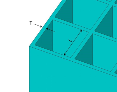
Data to provide in the value fields for Subtype =
BLOCK: |
T, L
|
| where: |
T = Thickness of the block wall. |
L = Spacing distance of the block walls. |
Type: SUPPORT, Subtype: ASEC
Data to provide in the value fields for Subtype =
ASEC: |
Thermal Structural
VAL1= Multiplication factor for KXX
VAL2= Multiplication factor for KYY
VAL3= Multiplication factor for KZZ
VAL4= Multiplication factor for DENS
VAL1= Multiplication factor for EX
VAL2= Multiplication factor for EY
VAL3= Multiplication factor for EZ
VAL4= Multiplication factor for GXY
VAL5= Multiplication factor for GYZ
VAL6= Multiplication factor for GXZ
VAL7= Multiplication factor for ALPX
VAL8= Multiplication factor for DENS
| The multiplication factors are homogenization factors, and in each direction reflect the ratio of the support area projected onto the area of a fully solid support. |
| Values default to 1.0. |
| Y and Z values default to X values. |
| GXY value defaults to EX value, GYZ to EY, and GXZ to EZ. |
Taper
Type: TAPER
Tapered sections are referenced by BEAM188, BEAM189 and ELBOW290 elements. After specifying the tapered section type (SECTYPE,,TAPER), issue separate SECDATA commands to define each end of the tapered beam or pipe.
| Data to provide in the value fields: |
Sec_IDn, XLOC, YLOC, ZLOC
|
where: Sec_IDn= Previously defined beam or pipe section at ends 1 and 2.XLOC,YLOC,ZLOC= The location of Sec_IDn in the global Cartesian coordinate system.
For more information about tapered beams and pipes, including assumptions and example command input, see Defining a Tapered Beam or Pipe in the Structural Analysis Guide.