


MPC184-Spotweld
Multipoint Constraint Element: Spotweld Joint
MPC184 Spotweld Joint Element Description
The MPC184 Spotweld joint is a two-node element used primarily for modeling spotweld behavior. The element requires a specified stiffness and/or damping at the element center. The relative degrees of freedom are unconstrained.
MPC184 Spotweld Joint Input Data
Set KEYOPT(1) = 18 to define a two-node spotweld joint element.
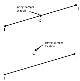
Figure 184spwd.1: MPC184 Spotweld Joint Geometry shows the geometry and node locations for this element. The local coordinate systems can be specified in either of the following ways:
The specified local coordinate systems are used in the spring/damping calculations.
By default, the location of the center (where the spring or damping behavior is active) is located midway between nodes I and J. The center location can be changed as follows:
Issue SECJOINT,SPWE,RATIO,
Val2(where 0≤Val2≤ 1). The location of the center is determined based on the locations of nodes I and J and the specified value.Issue SECJOINT,SPWE,COORD,
Val2,Val3,Val4(whereVal2,Val3,Val4represent the global X,Y,Z coordinates of the center). This option enables you to offset the center away from the line joining nodes I and J.
The relative displacements and rotations between nodes I and J are determined in the same way as for general joints.
The reference lengths and angles 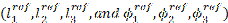 are not used in spotweld joint calculations.
MPC184 Spotweld Joint Input Summary
This input summary applies to the spotweld joint element form of MPC184: KEYOPT(1) = 18.
- Nodes
I, J
- Degrees of Freedom
UX, UY, UZ, ROTX, ROTY, ROTZ
- Real Constants
None
- Material Properties
Issue TB,JOIN to define stiffness and damping behavior. (See MPC184 Joint in the Material Reference for information about defining joint materials.)
- Surface Loads
None
- Body Loads
- Temperatures --
T(I), T(J)
- Element Loads
- Displacements/Rotations --
UX, UY, UZ, ROTX, ROTY, ROTZ
- Velocities --
VELX, VELY, VELZ, OMGX, OMGY, OMGZ
- Accelerations --
ACCX, ACCY, ACCZ, DMGX, DMGY, DMGZ
- Forces/Moments --
FX, FY, FZ, MX, MY, MZ
- Special Features
- KEYOPT(1)
Element behavior:
- 18 --
Spotweld joint element
- KEYOPT(2)
Element constraint-imposition method:
- 0 --
Lagrange multiplier method (default)
- 1 --
Penalty-based method
MPC184 Spotweld Joint Output Data
The solution output associated with the element is in two forms:
Nodal displacements included in the overall nodal solution.
Additional element output as shown in Table 184spwd.1: MPC184 Spotweld Joint Element Output Definitions and Table 184spwd.2: MPC184 Spotweld Joint Element - NMISC Output.
These tables use the following notation:
A colon (:) in the Name column indicates the item can be accessed by the Component Name method (ETABLE, ESOL). The O column indicates the availability of the items in the file Jobname.out. The R column indicates the availability of the items in the results file.
In either the O or R columns, Y indicates that the item is always available, a number refers to a table footnote that describes when the item is conditionally available, and a - indicates that the item is not available.
Table 184spwd.1: MPC184 Spotweld Joint Element Output Definitions
| Name | Definition | O | R |
|---|---|---|---|
| EL | Element number | - | Y |
| NODES | Element node numbers (I, J) | - | Y |
| The constraint force and moment output depends on which of the relative degrees of freedom are constrained: | |||
| FX | Constraint force in X direction | - | Y |
| FY | Constraint force in Y direction | - | Y |
| FZ | Constraint force in Z direction | - | Y |
| MX | Constraint moment in X direction | - | Y |
| MY | Constraint moment in Y direction | - | Y |
| MZ | Constraint moment in Z direction | - | Y |
| The following output depends on which of the relative degrees of freedom are unconstrained: | |||
| JRP1-6 | Joint relative position of DOFs 1-6 | - | Y |
| JCD1-6 | Joint relative position of DOFs 1-6 Joint constitutive displacement/rotation of DOFs 1-6 | - | Y |
| JEF1-6 | Joint elastic force/moment 1-6 | - | Y |
| JDF1-6 | Joint damping force/moment 1-6 | - | Y |
| JRU1-6 | Joint relative displacement/rotation 1-6 | - | Y |
| JRV1-6 | Joint relative velocity (or rotational velocity) 1-6 | - | Y |
| JRA1-6 | Joint relative acceleration (or rotational acceleration) 1-6 | - | Y |
| JTEMP | Average temperature in the element[a] | - | Y |
The following table shows additional non-summable miscellaneous (NMISC) output available for the spotweld joint element.
Note: This output is intended for use in the Ansys Workbench program to track the evolution of local coordinate systems specified at the joint element nodes.
Table 184spwd.2: MPC184 Spotweld Joint Element - NMISC Output
| Name | Definition | O | R |
|---|---|---|---|
| E1X-I, E1Y-I, E1Z-I | X, Y, Z components of the evolved e1 axis at node I | - | Y |
| E2X-I, E2Y-I, E2Z-I | X, Y, Z components of the evolved e2 axis at node I | - | Y |
| E3X-I, E3Y-I, E3Z-I | X, Y, Z components of the evolved e3 axis at node I | - | Y |
| E1X-J, E1Y-J, E1Z-J | X, Y, Z components of the evolved e1 axis at node J | - | Y |
| E2X-J, E2Y-J, E2Z-J | X, Y, Z components of the evolved e2 axis at node J | - | Y |
| E3X-J, E3Y-J, E3Z-J | X, Y, Z components of the evolved e3 axis at node J | - | Y |
| JFX, JFY, JFZ | Constraint forces expressed in the evolved coordinate system specified at node I | - | Y |
| JMX, JMY, JMZ | Constraint moments expressed in the evolved coordinate system specified at node I | - | Y |
Table 184spwd.3: MPC184 Spotweld Joint Item and Sequence Numbers - SMISC Items and Table 184spwd.4: MPC184 Spotweld Joint Item and Sequence Numbers - NMISC Items list output available via ETABLE using the Sequence Number method. See The General Postprocessor (POST1) in the Basic Analysis Guide and The Item and Sequence Number Table for further information. The table uses the following notation:
- Name
Output quantity as defined in the Element Output Definitions table
- Item
Predetermined Item label for ETABLE command
- E
Sequence number for single-valued or constant element data
Table 184spwd.4: MPC184 Spotweld Joint Item and Sequence Numbers - NMISC Items
| Output Quantity Name | ETABLE and ESOL Command Input | |
|---|---|---|
| Item | E | |
| E1X-I | NMISC | 1 |
| E1Y-I | NMISC | 2 |
| E1Z-I | NMISC | 3 |
| E2X-I | NMISC | 4 |
| E2Y-I | NMISC | 5 |
| E2Z-I | NMISC | 6 |
| E3X-I | NMISC | 7 |
| E3Y-I | NMISC | 8 |
| E3Z-I | NMISC | 9 |
| E1X-J | NMISC | 10 |
| E1Y-J | NMISC | 11 |
| E1Z-J | NMISC | 12 |
| E2X-J | NMISC | 13 |
| E2Y-J | NMISC | 14 |
| E2Z-J | NMISC | 15 |
| E3X-J | NMISC | 16 |
| E3Y-J | NMISC | 17 |
| E3Z-J | NMISC | 18 |
| JFX | NMISC | 19 |
| JFY | NMISC | 20 |
| JFZ | NMISC | 21 |
| JMX | NMISC | 22 |
| JMY | NMISC | 23 |
| JMZ | NMISC | 24 |
MPC184 Spotweld Joint Assumptions and Restrictions
Boundary conditions cannot be applied on the nodes forming the spotweld joint.
Rotational degrees of freedom are activated at the nodes forming the element. When these elements are used with solid elements, the rotational degrees of freedom must be suitably constrained. Because boundary conditions cannot be applied to the nodes of the weld joint, a beam or shell element with very weak stiffness can be used with the underlying solid elements at the nodes forming the joint element to avoid any rigid body modes.
In a nonlinear analysis, the components of relative motion are accumulated over all substeps. It is essential that the substep size be restricted such that these rotations in a given substep are less than π for the values to be accumulated correctly.
Element birth and death options are not available.
For the Lagrange multiplier element formulation (KEYOPT(2) = 0) and the penalty-based element formulation (KEYOPT(2) = 1), the equation solver (EQSLV) must be the sparse or PCG solver.
Lagrange multiplier-based joint elements (KEYOPT(2) = 0) and penalty-based joint elements (KEYOPT(2) = 1) cannot be connected to each other.
The element coordinate system (/PSYMB,ESYS) is not relevant.