Before you generate a mesh of nodes and elements, you must first define the appropriate element attributes. That is, you must specify the following:
The element type
Real constant set (usually comprising the element's geometric properties, such as thickness or cross-sectional area)
Material properties set (such as Young's modulus, thermal conductivity, etc.)
Element coordinate system
Section ID (current-technology beam elements only--see Generating a Beam Mesh With Orientation Nodes)
For beam meshing only, you may also specify orientation keypoints as attributes of a line. Generating a Beam Mesh With Orientation Nodes describes beam meshing in detail.
To assign attributes to your elements, you must first build tables of element attributes. Typical models include element types (ET command), real constants (R command), and material properties (MP and TB family of commands).
A table of coordinate systems can also be assembled using commands such as LOCAL, CLOCAL, etc. This table can be used to assign element coordinate systems to elements. (Not all element types can be assigned a coordinate system in this manner. See Element Coordinate Systems of this manual for information about element coordinate systems. For element descriptions, see the Element Reference.)
For beam meshing with BEAM188 or BEAM189 elements, you can build a table of sections using the SECTYPE and SECDATA commands.
|
Orientation keypoints are attributes of a line. They are not element attributes. You cannot create tables of orientation keypoints. See Assigning Element Attributes Before Meshing for more information. |
The element attribute tables described above can be visualized as shown in Figure 7.2: Element Attribute Tables. (For more information on creating your element attribute tables, see Getting Started in the Basic Analysis Guide.)

You can review the contents of the element type, real constant, and material tables by issuing the ETLIST (TYPE table), RLIST (REAL table), or MPLIST (MAT table) commands. You can review the coordinate system table by issuing CSLIST. You can review the section table by issuing SLIST.
Once the attribute tables are assembled, you can assign element attributes to different parts of your model by "pointing" to the appropriate entries in the tables. The pointers are simply a set of reference numbers that include a material number (MAT), a real constant set number (REAL), an element type number (TYPE), a coordinate system number (ESYS) and, for beam meshing with BEAM188, or BEAM189, a section ID number (SECNUM). You can either assign the attributes directly to selected solid model entities, or define a default set of attributes that will be used for elements created in subsequent meshing operations.
Note: As stated earlier, although you can assign orientation keypoints as attributes of a line for beam meshing, you cannot build tables of orientation keypoints. Therefore, to assign orientation keypoints as attributes, you must assign them directly to selected lines. You cannot define a default set of orientation keypoints to be used in subsequent meshing operations. See Generating a Beam Mesh With Orientation Nodes for details about assigning orientation keypoints.
Assigning the element attributes to the solid model entities allows you to preassign attributes for each region of your model. By using this method, you can avoid having to reset attributes in the middle of meshing operations. (Clearing a solid model entity of its nodes and elements will not delete attributes assigned directly to the entity.)
Use the commands listed below to assign attributes directly to solid model entities.
You can assign a set of default attributes by simply pointing to various entries in the attribute tables. The pointers that are in effect at the time you create your elements (that is, when you initiate meshing) are used by the program to assign attributes from the tables to the solid model and to the elements. Attributes assigned directly to the solid model entities (as described above) will override the default attributes. Also, if you clear a solid model entity of its nodes and elements, any attributes that were assigned through default attributes will be deleted.
To assign a set of default attributes, use the TYPE, REAL, MAT, ESYS, or SECNUM commands.
In certain cases, the program can choose the correct element type for a meshing or extrusion operation, eliminating the need for you to manually switch between element types when the correct choice is obvious.
Specifically, if you fail to assign an element type directly to a solid model entity (xATT) and the default element type (TYPE) is not dimensionally correct for the operation that you want to perform, but there is only one dimensionally correct element type in the currently defined element attribute tables, Mechanical APDL automatically uses that element type to proceed with the operation.
The meshing and extrusion operations affected by this feature are KMESH, LMESH, AMESH, VMESH, FVMESH, VOFFST, VEXT, VDRAG, VROTAT, and VSWEEP.
You can define a thickness at nodes for shell elements (SECFUNCTION).
Shell elements can model complex distributions of thickness. For example, SHELL181 enables different thicknesses to be assigned at each of its four corner nodes. Each element assumes a smooth variation between the given corner values.
Defining a complicated thickness variation on a group of elements can be challenging. In the worst case, every element needs its own unique set of section thicknesses. In some such cases, SECFUNCTION can simplify model definition.
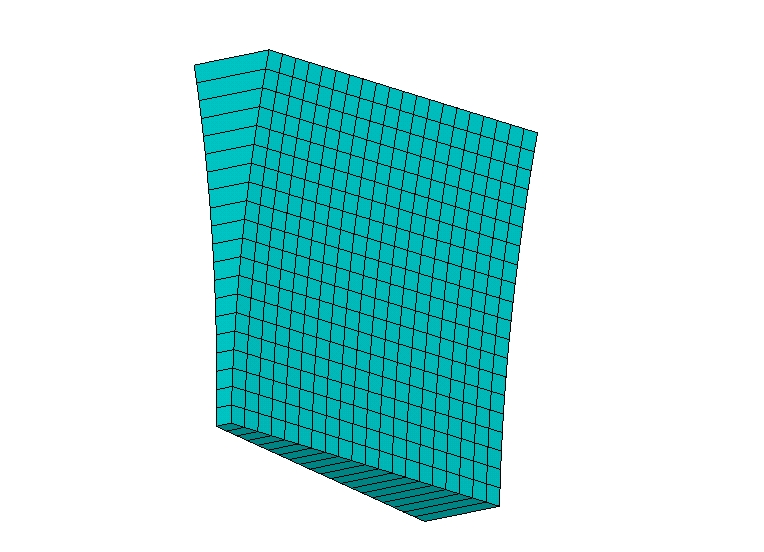
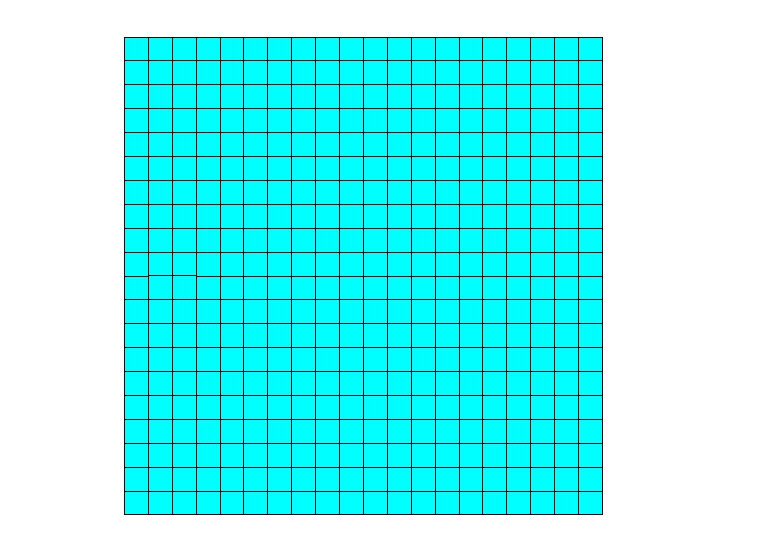
Example 7.1: Defining a 10 x 10 Rectangle Filled with 0.5 x 0.5 Square SHELL181 Elements
/TITLE, SECFUNCTION Example
/PREP7
ET,1,181,,,2
RECT,,10,,10
ESIZE,,20
AMESH,1
EPLO
The thickness should vary according to the formula: thickness = 0.5 + 0.2x + 0.02y2 .
Example 7.2: Creating an Array Parameter Mapping Thickness to Node Number
*GET,MXNODE,NODE,,NUM,MAXD
*DIM,THICK,,MXNODE,2
*DO,NODE,1,MXNODE
   *IF,NSEL(NODE),EQ,1,THEN
      THICK(node,1) = node
      THICK(node,2) = 0.5 + 0.2*NX(NODE) + 0.02*NY(NODE)**2
   *ENDIF
*ENDDO
NODE = $ MXNODE =
Finally, assign the thickness in the array parameter to the elements (SECFUNCTION).
Example 7.3: Assigining the Thickness to the Elements
SECTYPE,1,SHELL
SECFUNCTION,%THICK%,NOD2
/ESHAPE,1.0  $ /USER,1  $ /DIST,1,7
/VIEW,1,-0.75,-0.28,0.6  $ /ANG,1,-1
/FOC,1,5.3,5.3,0.27  $ EPLO