


There are two primary main types of beam cross sections:
Common sections
Custom sections
Common sections are described by a standard geometry and a single material. Custom sections are defined by an arbitrary geometry and may consist of several materials.
In addition, you can use defined sections to create tapered beams (for BEAM188, BEAM189, and ELBOW290 only). See Defining a Tapered Beam or Pipe for more information.
The following topics related to creating cross sections are available:
- 12.3.1. Using the Beam Tool to Create Common Cross Sections
- 12.3.2. Creating Custom Cross Sections with a User-Defined Mesh
- 12.3.3. Creating Custom Cross Sections with Mesh Refinement and Multiple Materials
- 12.3.4. Defining Composite Cross Sections
- 12.3.5. Defining a Tapered Beam or Pipe
- 12.3.6. Defining a Noncircular Pipe
The SECTYPE, SECDATA, and SECOFFSET commands () are all associated with the BeamTool in the GUI. The appearance of the BeamTool varies depending on the cross section subtype you select:
The top part of the BeamTool relates a section ID number to a subtype (and, optionally, a section name) (SECTYPE). The middle of the BeamTool defines the section offset information, if needed (SECOFFSET). The bottom contains the fields for section geometry information (SECDATA). The dimensions defined by the SECDATA command are determined by the subtype selected. For documentation about a particular variant of the BeamTool, select the subtype that you want information about, and then click the button on the BeamTool. The subtype dimensions are also documented in the SECDATA command description.
If you need to define a cross section that is not common, you must create a user mesh file. To create a user mesh file, create a 2D solid model and save it using the SECWRITE command (). This procedure is outlined in greater detail below:
Create all areas ().
Overlap the areas () or glue them () where appropriate.
Save the model.
Set the number of line divisions for all lines ( or use the MeshTool).
Select . A picker appears. Pick the area(s) of the cells.
The program creates cells on the areas. Bad shape messages may appear during the mesh, but you can ignore them. You may, however, see an "Unable to mesh area ...." message; if you do, clear the elements from all areas () and repeat steps 4 and 5.
Write the .SECT file out to a unique name in the Write Section Library File dialog and click .
Read in the user mesh file () to calculate the section properties. Material properties must be defined to calculate the cross section shear correction factors, material-weighted centroids and the shear centers.
Even if you have already set the line element size (LESIZE), you will see the following message:
Line element sizes may need to be specified for desired cross-section mesh. (See LESIZE.)
If you have already set the line element size, click the button to continue. If you have not already set it, issue LESIZE with the appropriate information.
When creating cells on the area using the GUI, it is not necessary to define a plane element type. On the other hand, you must define a plane element type and mesh the area if you issue the SECWRITE command explicitly. MESH200 with KEYOPT(1) = 7 and PLANE183 are the only valid plane element types.
When performing a plasticity analysis, you may need to refine the cross section mesh. A cross section consisting of more than one material may be defined to represent layers, reinforcements or sensors. When defining a multiple-material cross section, you will need to specify the material that each cross section cell is made of. You can take a previously-created cross section and modify it.
To create a custom cross section with a refined mesh and/or multiple materials, perform the following tasks:
Read a common section () from the database, or read a custom section from a .SECT file. ()
The Graphics window displays a MESH200 plot.
Refine the section mesh. ()
Modify the cell materials. () If you want to create a multiple-material section, define the materials. This is necessary to calculate the shear correction factors and material-weighted centroids.
Save the section to a .SECT file using SECWRITE ().
Calculate the section properties and use a custom section in the analysis by reading in the user mesh file ().
Note: If you redefine a material after creating the section, you must reissue the SECTYPE and SECREAD commands to recalculate the cross section.
When a cross section has multiple materials, and /ESHAPE is used to produce contour plots of stresses (and other quantities), the element averages the stresses across material boundaries. To limit this behavior, use small cross section cells around the material boundaries.
When using the SECWRITE command explicitly, a section with multiple materials can be created by assigning material attributes to the areas. During meshing, the elements inherit the material attribute from the area and this attribute is written to the .SECT file.
A material number (MAT) specified for a custom section overrides any existing material setting.
A composite cross section is a cross section consisting of at least two materials and meshed with a user-defined mesh. When creating a composite section, define the materials before running the SECREAD command. This is necessary to calculate the shear correction factors, material-weighted centroids and the shear centers.
If you redefine a material after creating the section, you must reissue the SECREAD command to recalculate the cross section.
You can save composite cross sections as custom cross sections. For more information, see Using the Beam Tool to Create Common Cross Sections
Using BEAM188, BEAM189 and ELBOW290 elements, you can define tapered sections via SECTYPE command’s TAPER option (). The tapered section varies linearly between two specified locations, (x1, y1, z1) and (x2, y2, z2); therefore, two SECDATA commands are necessary to define the taper:
Specify valid beam section IDs (station1 and
station2) for both end points.
Example 12.1: Creating a Tapered Cross Section
The following is a typical command input stream used to create a tapered cross section:
sectype,1,beam,rect     ! define cross section at first end point
secdata,.0001,0.5
sectype,2,beam,rect     ! define cross section at far end
secdata,3,0.5
sectype,3,taper         ! new Section ID for tapered beam analysis
secdata,1,0.0,0.0       ! section 1 at location (0,0,0)
secdata,2,0.0,20.0      ! section 2 at location (0,20,0)
Continuing with this example, you can then use 3 as the taper section ID when assigning mesh attributes (SECNUM or LATT). The resulting beam cross section is (0.0001 * 0.5) at end 1, and linearly tapers to (3 * 0.5) at end 2.
The following assumptions apply to tapered beams or pipes defined using this method:
The end sections must be defined prior to defining the taper.
Sections defined at the end points must be topologically identical. For a tapered pipe, end points must have the same number of cells around the circumference and through the pipe wall. For a tapered composite pipe, end points must have the same shell section ID.
A section cannot taper to a point (or zero area) at either end.
The arbitrary beam section type (SECTYPE,,BEAM,ASEC) assumes a linear variation of properties along the length; large differences in properties between the ends are not recommended.
The program performs a number of checks (although not completely comprehensive) to ensure topological equality. The following items are compared:
Number of section nodes
Number of section elements
Section type
Number of cells about the circumference and through the thickness for a tapered pipe
Shell section ID for a tapered composite pipe
If both end stations refer to custom cross sections with multiple materials, that material IDs for the cells are the same for both ends.
At a Gauss point of integration, the BEAM188,
BEAM189 and ELBOW290 elements
will find the closest point on the line defined by
station1 and station2.
Using this information, a linear interpolation is performed for the cross section
mesh. The Gauss point must therefore be located within the end points. A Gauss point
within a specified tolerance
(SELTOL,TOLER) is considered to be
coincident with an end station. The default tolerance value is 1.0E-8.
The tapered section treatment is significantly more computation-intensive than a constant cross section (as recalculation is necessary). If computational cost is a concern, use KEYOPT(12) of the beam element to specify the tapered section treatment:
KEYOPT(12) = 0 - Linear tapered section analysis (more accurate, but expensive)
KEYOPT(12) = 1 - Average cross section analysis (an approximation of the order of the mesh size, but faster)
KEYOPT(12) does not apply to the ELBOW290 element.
Using the ELBOW290 element, you can define a noncircular
pipe section via the SECTYPE command’s PIPE option
(). The
geometry and other data are specified via a subsequent SECDATA
command. For a circular pipe, the SECDATA command’s
Do value (outside diameter) requires only a constant
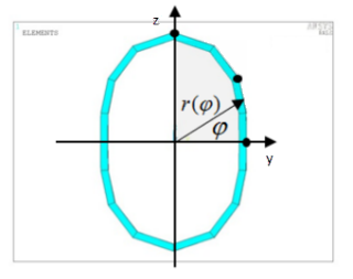
value. A two-dimensional array represents the outside profile of a noncircular
pipe.
Example 12.2: Outside Profile of a Noncircular Pipe
*dim,radius,,2,3   ! Declare a 2 * 3 array
radius(1,1) = 0    ! Angle (in degrees) of the 1st point
radius(2,1) = 1.0  ! Radial coordinate of the 1st point
radius(1,2) = 45.0 ! Angle of the 2nd point
radius(2,2) = 1.25 ! Radial coordinate of the 2nd point
radius(1,3) = 90   ! Angle of the 3rd point
radius(2,3) = 1.5  ! Radial coordinate of the 3rd point
SECT, 1, PIPE
SECD, %radius%, 0.1, 16 ! Input the array name in the Do field
Because of the symmetry involved, only locations in coordinate phase one (0 <
 < 90) are required for this example of an oval pipe section:
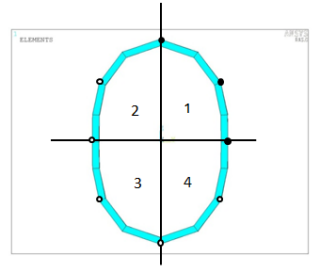
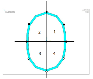
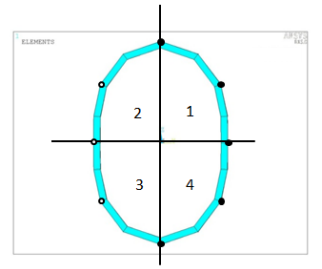
An illustration of general symmetry expansion rules follows. In these figures, the solid circles represent user-input data, and the open circles are data created automatically based on symmetry assumptions:
The following considerations apply to noncircular pipe sections:
They are recommended only for sections having a smooth profile.
A data-modeling procedure is adopted to obtain interpolation function to describe the smooth section profile. It may be necessary to define more points for irregular geometry; however, for highly irregular geometry, an accurate interpolation may not be achievable even with more data points. Always verify the sections created.
A noncircular pipe section can be visualized via SECPLOT.
Circular and noncircular pipe sections are topologically identical.
Both circular and noncircular pipes can be used as the end points of a tapered pipe section, allowing great flexibility for defining generalized tubular structures.