


CABLE280
3D Cable
CABLE280 Element Description
CABLE280 is suitable for analyzing moderate to extremely slender cable structures (such as undersea cables). The element is a quadratic three-node line element in 3D space. Each node has three degrees of freedom: translations in the nodal x, y, and z directions.
Elasticity, isotropic hardening plasticity, kinematic hardening plasticity, Hill anisotropic plasticity, Chaboche nonlinear hardening plasticity, and creep are supported. Added mass, damping, compressive stiffness scaling, viscous regularization, and initial state are available.
For more information about this element, see CABLE280 - 3D 3-Node Cable in the Theory Reference.
CABLE280 Technology and Usage Recommendations
CABLE280 is based on a mixed-displacement and axial-force (U-F) formulation: quadratic approximation for displacement and linear approximation for internal axial forces (user-inaccessible). Axial forces are incompatible (that is, axial forces can be discontinuous from element to element).
The highly nonlinear behavior of the element requires an iterative-solution approach (NLGEOM,ON) for static and transient simulation. The element requires tensile stress to provide adequate transverse stiffness. Solution processing may become unstable when the elements are insufficiently loaded or in a compressive state.
The advanced formulation of CABLE280 (in comparison to other conventional line elements such as LINK180, BEAM188, and BEAM189) enables excellent mesh convergence and an accurate solution with coarse discretization.
CABLE280 Input Data
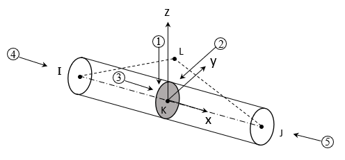
The geometry, node locations, and coordinate system for this element are shown in Figure 280.1: CABLE280 Geometry. The element is defined by nodes I, J, and K in the global coordinate system.
Section orientation (the y-z local coordinate plane) is required only for defining distributed loads. Node L is the preferred way to define the section orientation of the element. Defining cable elements with orientation nodes is the same as for beam elements. For information about generating node L automatically, see LMESH and LATT.
The element can also be defined without the orientation node L. In this case, the element x axis is oriented from node I (end 1) toward node J (end 2). Without node L, the default orientation of the element y axis is parallel to the global X-Y plane.
If the element is parallel to the global Z axis (or within a 0.01 percent slope of it), the element y axis is oriented parallel to the global Y axis (as shown). To control the element orientation about the element x axis, use node L. If both are defined, node L takes precedence. If used, node L defines a plane (with I and J) containing the element x and z axes (as shown).
If using this element in a large-deflection analysis, the location of node L serves only to orient the element initially.
By default, the element allows the cross-sectional area to change as a function of axial elongation; therefore, the volume of the element is preserved even after deformation. The default behavior is suitable for elastoplastic applications. (You can also maintain a constant or rigid cross-section via KEYOPT(2) = 1.)
CABLE280 is a 1D line element in space. It can be associated with a link section. The cross-section details are defined separately (SECTYPE and SECDATA). A section is associated with the cable element via the section ID number (SECNUM).
Element loads are described in Element Loading. Temperatures can be input as element body loads at the nodes. The node I temperature T(I) defaults to TUNIF. The node J temperature T(J) defaults to T(I).
The element ignores real constant data.
Mass Matrix
For the mass matrix and evaluation of consistent load vectors, the element uses a
higher-order integration rule than that used for the stiffness matrix. The element supports both
consistent and lumped mass matrices. (Do not specify a lumped mass matrix formulation
(LUMPM,ON), as CABLE280 is a higher-order element.)
Consistent mass matrix is used by default. You can add mass per unit length
(SECCONTROL,ADDMAS).
Damping
The damping portion of the element contributes only damping coefficients to the structural
damping matrix. The damping force  is given by:

where  is the damping coefficient given by
  , where
  is the velocity calculated in the previous substep.
The second damping coefficient  is available to produce a nonlinear damping effect characteristic of some
fluid environments. The damping coefficient units are Force *
Time / Length.
is available to produce a nonlinear damping effect characteristic of some
fluid environments. The damping coefficient units are Force *
Time / Length.
Input damping coefficients via
SECCONTROL,,,CV1,CV2.
Compressive Stiffness Scaling
CABLE280 supports tension-only cable simulations.
(SECCONTROL,,TENSKEY is therefore not valid.) A
small compressive stiffness is required, however, for a robust nonlinear solution. The
compressive stiffness is given as a fraction of the tensile stiffness
(SECCONTROL,,,,,CV3).
Viscous Regularization
The element uses viscous regularization to overcome convergence difficulties which may arise when a cable switches from tension to compression (or vice versa). Viscous regularization of stiffness is given by:

where  is the stiffness before viscous regularization,
 is the stiffness after viscous regularization, and
 is the viscous regularization factor
(SECCONTROL,,,,,,
is the viscous regularization factor
(SECCONTROL,,,,,,CV4). The default viscous
regularization factor is 0.05.
Initial State
You can apply an initial stress state to this element (INISTATE). For more information, see Initial State in the Advanced Analysis Guide.
CABLE280 Input Summary
For a general description of element input, see Element Input.
- Nodes
I, J, K, L (the orientation node L is optional but recommended)
- Degrees of Freedom
UX, UY, UZ
- Material Properties
TB command: See Element Support for Material Models for this element.
MP command: EX, (PRXY or NUXY), ALPX (or CTEX or THSX), DENS, GXY, ALPD, BETD, DMPR, DMPS
- Surface Loads
- Pressure --
face 1 (I-J) (-z normal direction)
face 2 (I-J) (-y normal direction)
face 3 (I-J) (+x tangential direction)
face 4 (I) (+x axial direction)
face 5 (J) (-x axial direction)
---
I and J denote the end nodes.
Use a negative value for loading in the opposite direction.
Specify surface loads via SFBEAM.
- Body Loads
- Temperatures --
T(I), T(J)
- Special Features
- KEYOPT(2)
Cross-section scaling:
- 0 --
Enforce incompressibility; cross-section is scaled as a function of axial stretch (default).
- 1 --
Section is assumed to be rigid.
CABLE280 Output Data
The solution output associated with the element is in two forms:
Nodal displacements included in the overall nodal solution
Additional element output as shown in Table 280.1: CABLE280 Element Output Definitions.
A general description of solution output is given in Solution Output. Element results can be viewed in POST1 via PRESOL,ELEM.
The Element Output Definitions table uses the following notation:
A colon (:) in the Name column indicates that the item can be accessed by the Component Name method (ETABLE, ESOL). The O column indicates the availability of the items in the file jobname.out. The R column indicates the availability of the items in the results file.
In either the O or R columns, Y indicates that the item is always available, a number refers to a table footnote that describes when the item is conditionally available, and - indicates that the item is not available.
Table 280.1: CABLE280 Element Output Definitions
| Name | Definition | O | R |
|---|---|---|---|
| EL | Element number | Y | Y |
| NODES | Element connectivity | Y | Y |
| MAT | Material number | Y | Y |
| SECID | Section number | Y | - |
| XC, YC, ZC | Center location | Y | 1 |
| TEMP | Temperatures T(I), T(J), T(K) | Y | Y |
| AREA | Cross-sectional area | Y | Y |
| FORCE | Member force in the element coordinate system | Y | Y |
| Sxx | Axial stress | Y | Y |
| EPELxx | Axial elastic strain | Y | Y |
| EPTOxx | Total strain | Y | Y |
| EPEQ | Plastic equivalent strain | 2 | 2 |
| Cur.Yld.Flag | Current yield flag | 2 | 2 |
| Plwk | Plastic strain energy density | 2 | 2 |
| Creq | Creep equivalent strain | 2 | 2 |
| Crwk_Creep | Creep strain energy density | 2 | 2 |
| EPPLxx | Axial plastic strain | 2 | 2 |
| EPCRxx | Axial creep strain | 2 | 2 |
| EPTHxx | Axial thermal strain | 3 | 3 |
| NL:SEPL | Plastic yield stress | - | 4 |
| NL:SRAT | Plastic yielding (1 = actively yielding, 0 = not yeilding) | - | 4 |
| NL:HPRES | Hydrostatic pressure | - | 4 |
| NL:EPEQ | Accumulated equivalent plastic strain | - | 4 |
| NL:CREQ | Accumulated equivalent creep strain | - | 4 |
| NL:PLWK | Plastic work/volume | - | 4 |
Available only at the centroid as a *GET item.
Available only if the element has an appropriate nonlinear material.
Available only if the element temperatures differ from the reference temperature.
Table 280.2: CABLE280 Item and Sequence Numbers lists output available through ETABLE using the Sequence Number method. See The General Postprocessor (POST1) and The Item and Sequence Number Table in this reference for more information. The following notation is used in Table 280.2: CABLE280 Item and Sequence Numbers:
- Name
output quantity as defined in Table 280.1: CABLE280 Element Output Definitions
- Item
predetermined Item label for ETABLE and
- E
sequence number for single-valued or constant element data
- I,J
sequence number for data at nodes I and J
This item is not available via ESOL.
CABLE280 Assumptions and Restrictions
The length of the cable must be greater than zero.
The cross-sectional area must be greater than zero.
The temperature is assumed to vary linearly along the length of the element.
A nonlinear iterative solution (NLGEOM,ON) is required for static and transient simulation.
CABLE280 Product Restrictions
When used in the product(s) listed below, the stated product-specific restrictions apply to this element in addition to the general assumptions and restrictions given in the previous section.
Ansys Mechanical Pro —
Birth and death is not available.
Initial state is not available.
Ansys Mechanical Premium —
Birth and death is not available.