


MESH200
Meshing
Facet
MESH200 Element Description
MESH200 is a special mesh-only element, contributing nothing to the solution. The element can be used for the following types of operations:
Multistep meshing operations, such as extrusion, that require a lower dimensionality mesh be used for the creation of a higher dimensionality mesh
Line-meshing in 2D or 3D space with or without midside nodes,
Area-meshing or volume-meshing in 3D space with triangles, quadrilaterals, tetrahedra, or bricks, with or without midside nodes.
Temporary storage of elements when the analysis physics has not yet been specified.
Temporary representation of discrete reinforcing fibers and smeared reinforcing layers, including their geometry, material, and orientation. The following element options are available for reinforcing modeling:
2D lines with two or three nodes for smeared reinforcing in 2D
3D Lines with two or three nodes for discrete reinforcing in 3D
3D triangle with three or six nodes, or quadrilateral with four or eight nodes, for smeared reinforcing in 3D
For more information about modeling reinforcing structural members with MESH200 elements, see Reinforcing and Direct Element Embedding in the Structural Analysis Guide.
MESH200 can be used with any other element type. After it is no longer needed, it can be deleted (cleared), or can be left in place. Its presence does not affect solution results.
MESH200 elements can be changed into other element types via EMODIF.
In a reinforcing analysis using the mesh-independent method, you can:
Apply an initial state to the MESH200 elements. Mechanical APDL then transfers the initial state to all newly created REINF263, REINF264, or REINF265 reinforcing elements automatically.
Apply heat-generation loading to the MESH200 elements in a thermal reinforcing analysis. Mechanical APDL then maps the heat-generation loads to the newly generated REINF264 or REINF265 reinforcing elements automatically.


MESH200 Input Data
The geometry and node locations supported for this element are shown in
Figure 200.1: MESH200 Geometry. The element is defined by two to twenty nodes. It has no degrees
of freedom, material properties, real constants, or loadings. When the element is used for reinforcing modeling, you can assign material properties by
specifying a material ID (SECDATA,MAT).
"MESH200 Input Summary" summarizes the element input. See Element Input in the Element Reference for a general description of element input.
MESH200 Input Summary
- Nodes
I, J if KEYOPT (1) = 0, 2D line with 2 nodes I, J, K if KEYOPT (1) = 1, 2D line with 3 nodes I, J if KEYOPT (1) = 2, 3D line with 2 nodes I, J, K if KEYOPT (1) = 3, 3D line with 3 nodes I, J, K if KEYOPT (1) = 4, 3D triangle with 3 nodes I, J, K, L, M, N if KEYOPT (1) = 5, 3D triangle with 6 nodes I, J, K, L if KEYOPT (1) = 6, 3D quadrilateral with 4 nodes I, J, K, L, M, N, O, P if KEYOPT (1) = 7, 3D quadrilateral with 8 nodes I, J, K, L if KEYOPT (1) = 8, tetrahedron with 4 nodes [1] I, J, K, L, M, N, O, P, Q, R if KEYOPT (1) = 9, tetrahedron with 10 nodes [1] I, J, K, L, M, N, O, P if KEYOPT (1) = 10, brick with 8 nodes [1] I, J, K, L, M, N, O, P, Q, R, S, T, U, V, W, X, Y, Z, A, B if KEYOPT (1) = 11, brick with 20 nodes [1] Not used for reinforcing modeling.
- Degrees of Freedom
None
- Real Constants
None
- Section
When used for reinforcing modeling: Reinforcing section to define the material ID, fiber cross-section area, fiber spacing (smeared), and fiber orientation (smeared). See SECTYPE and SECDATA. When used for other applications: None - Material Properties
When used for reinforcing modeling: All materials supported by reinforcing elements (REINF263, REINF264, and REINF265). The element material ID is recognized only when the material ID value ( MAT) on the SECDATA command is blank.When used for other applications: None - Element Coordinate System
When used for reinforcing modeling: The default orientation is defined by the first parametric direction S1. The x axis indicates the fiber orientation, expressed as: where: 
When generating 2D and 3D smeared reinforcing elements, you can reorient the element coordinate system by: - Defining a local coordinate reference number ( KCNon ESYS or SECDATA)- Defining the orientation angle ( THETAon SECDATA)- Combining the above two methods. 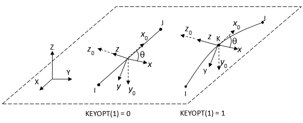
X,Y,Z: Global coordinate system x0, y0, z0: Default element coordinate system x, y, z: Element coordinates when element orientation ( KCNand/orTHETA) is specified.θ: Orientation angle defined by KCNand/orTHETA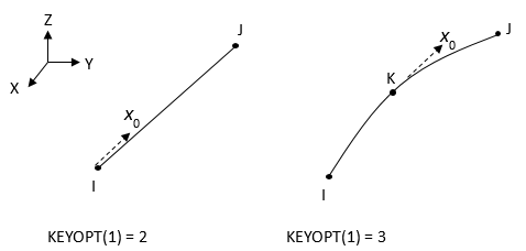
X,Y,Z: Global coordinate system x0: Default element coordinate system (For 3D line elements, KCN and THETA are not used for generating reinforcing elements.) 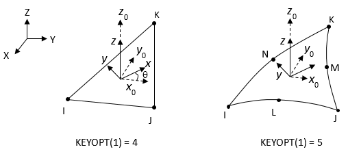
X,Y,Z: Global coordinate system x0, y0, z0: Default element coordinate system x, y, z: Element coordinates when element orientation ( KCNand/orTHETA) is specified.θ: Orientation angle defined by KCNand/orTHETA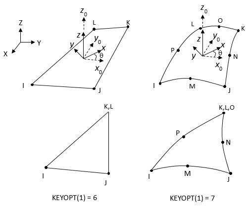
X,Y,Z: Global coordinate system x0, y0, z0: Default element coordinate system x, y, z: Element coordinates when element orientation ( KCNand/orTHETA) is specified.θ: Orientation angle defined by KCNand/orTHETAWhen used for other applications: None

- Surface Loads
None
- Body Loads
When used for reinforcing modeling: Heat Generations – HG(I), HG(J) – KEYOPT(1) = 0, 1, 2, 3, 2D / 3D line HG(I), HG(J), HG(K) – KEYOPT(1) = 4, 5, 3D triangle HG(I), HG(J), HG(K), HG(L) – KEYOPT(1) = 6 ,7, 3D quadrilateral When using the mesh-independent method for defining reinforcing (where the MESH200 elements are used to generate the reinforcing elements), you can apply heat generation on the MESH200 elements via BFE (element body-force loading) or BF (nodal body-force loading). Body-Force Density – The element values in the global X and Y directions -- KEYOPT(1) = 0, 1, 2D The element values in the global X, Y, and Z directions -- KEYOPT(1) = 2, 3, 4, 5, 6, 7, 3D When using the mesh-independent method for defining reinforcing (where the MESH200 elements are used to generate the reinforcing elements), you can apply body-force density on the MESH200 elements via BFE (element body-force loading). When used for other applications: None - Special Features
- KEYOPT(1)
Element shape and number of nodes:
- 0 --
2D line with 2 nodes
- 1 --
2D line with 3 nodes
- 2 --
3D line with 2 nodes
- 3 --
3D line with 3 nodes
- 4 --
3D triangle with 3 nodes
- 5 --
3D triangle with 6 nodes
- 6 --
3D quadrilateral with 4 nodes
- 7 --
3D quadrilateral with 8 nodes
- 8 --
Tetrahedron with 4 nodes
- 9 --
Tetrahedron with 10 nodes
- 10 --
Brick with 8 nodes
- 11 --
Brick with 20 nodes
- KEYOPT(2)
Element shape testing:
- 0 --
Shape testing is done (default)
- 1 --
No shape testing is done for this element
MESH200 Assumptions and Restrictions
When this element is a triangle or quadrilateral, it is shape-tested in the same manner as an equivalent "non-structural shell". When it is a tetrahedron or brick, it is shape-tested like a SOLID185. This is so that meshing will work to create well-shaped elements. If KEYOPT(2) = 1, no shape testing is done for this element type.
MESH200 elements may not be active during result contour plotting (/POST1, PLNSOL, or PLESOL). The elements are automatically unselected during either operation.