


LINK33
3D Conduction
Bar
LINK33 Element Description
LINK33 is a uniaxial element in 3D space with the ability to conduct heat between its nodes. The element has a single degree of freedom, temperature, at each node point. This element is applicable to a steady-state or transient thermal analysis.
If the model containing this conducting bar element is also to be analyzed structurally, the bar element should be replaced by an equivalent structural element. See LINK33 in the Mechanical APDL Theory Reference for more details about this element.
LINK33 Input Data
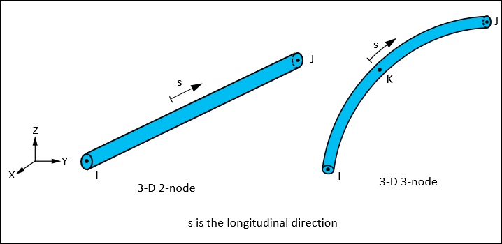
The geometry, node locations, and the coordinate system for this element are shown in Figure 33.1: LINK33 Geometry. The element is defined by its configuration (two or three nodes, prescribed by setting KEYOPT(4) = 0 or 1, respectively), a cross-sectional area input via the SECTYPE and SECDATA commands, and the material properties. Specific heat and density are ignored for steady-state solutions. The thermal conductivity is in the element longitudinal s direction.
Element loads are described in Element Loading. Heat generation rates may be input as element body loads at the nodes. The node J heat generation rate HG(J) defaults to the node I heat generation rate HG(I) for the 2-node element. The node J and K heat generation rate HG(J) and HG(K) defaults to the node I heat generation rate HG(I) for the 3-node element.
The element can represent a reduced order model in place of solid 3D or planar 2D elements. For example, the 3-node configuration can be used to replace SOLID279 and the 2-node configuration can replace SOLID278.
A summary of the element input is given in "LINK33 Input Summary". A general description of element input is given in Element Input.
LINK33 Input Summary
- Nodes
I, J for KEYOPT(4) = 0 I, J, K for KEYOPT(4) = 1 - Degrees of Freedom
TEMP
- Material Properties
MP command: KXX (Thermal conductivity in longitudinal s direction), DENS, C, ENTH
- Surface Loads
None
- Body Loads
- Heat Generation --
HG(I), HG(J) for KEYOPT(4) = 0 HG(I), HG(J), HG(K) for KEYOPT(4) = 1
- Special Features
- KEYOPT(4)
Specify 2-node or 3-node element:
- 0 --
2-node element
- 1 --
3-node element
LINK33 Output Data
The solution output associated with the element is in two forms:
Nodal temperatures included in the overall nodal solution
Additional element output as shown in Table 33.1: LINK33 Element Output Definitions
The heat flow rate is in units of Heat/Time and is positive from node I to node J. A general description of solution output is given in Solution Output. See the Basic Analysis Guide for ways to view results.
The Element Output Definitions table uses the following notation:
A colon (:) in the Name column indicates that the item can be accessed by the Component Name method (ETABLE, ESOL). The O column indicates the availability of the items in the file jobname.out. The R column indicates the availability of the items in the results file.
In either the O or R columns, “Y” indicates that the item is always available, a letter or number refers to a table footnote that describes when the item is conditionally available, and “-” indicates that the item is not available.
Table 33.1: LINK33 Element Output Definitions
| Name | Definition | O | R |
|---|---|---|---|
| EL | Element Number | Y | Y |
| NODES | Nodes - I, J for KEYOPT (4) = 0 Nodes - I,J, K for KEYOPT(4) = 1 | Y | Y |
| MAT | Material number | Y | Y |
| VOLU: | Volume | Y | Y |
| XC, YC, ZC | Location where results are reported | Y | 1 |
| LENGTH | Length | Y | Y |
| HGEN | HG(I), HG(J) for KEYOPT(4) = 0 HG(I), HG(J), HG(K) for KEYOPT(4) = 1 | Y | - |
| TG:X[a][b] | Thermal gradient along the longitudinal s direction | Y | Y |
| TF:X[a][b] | Thermal heat flux along the longitudinal s direction | Y | Y |
| AREA | Input area | Y | Y |
| TEMP(I, J) | Temperatures - I, J | Y | Y |
| Average HEAT RATE | Heat flow rate from node I to node J | Y | Y |
| Average THERMAL FLUX | Thermal flux (heat flow rate/cross-sectional area) | Y | Y |
[a] For the 2-node element (KEYOPT(4) = 0), values for TG and TF are constant with the same value at the end nodes. For the 3-node element (KEYOPT(4) = 1), values for TG and TF vary linearly with different values at the end nodes.
[b] For the 3-node element (KEYOPT(4) = 1), consider using the ERESX command to evaluate TG and TF (see "LINK33 Assumptions and Restrictions").
Available only at centroid as a *GET item.
Table 33.2: LINK33 Item and Sequence Numbers lists output available through the ETABLE command using the Sequence Number method. See The General Postprocessor (POST1) in the Basic Analysis Guide and The Item and Sequence Number Table in this reference for more information. The following notation is used in Table 33.2: LINK33 Item and Sequence Numbers:
- Name
output quantity as defined in the Table 33.1: LINK33 Element Output Definitions
- Item
predetermined Item label for ETABLE command
- E
sequence number for single-valued or constant element data
LINK33 Assumptions and Restrictions
Heat is assumed to flow only in the longitudinal element direction s.
The element must not have a zero length, so nodes I and J must not be coincident.
A free end of the element (that is, not adjacent to another element and not subjected to a boundary constraint) is assumed to be adiabatic.
For the 3-node element (KEYOPT(4) = 1), you can use the ERESX command to specify extrapolation of integration point results for the TG and TF values: