Three types of geometry correction are available:
In general, curved contact and target surfaces can be well approximated by linear (lower order) or quadratic (higher order) contact and target elements when the mesh is sufficiently refined. However, in certain circumstances this is not the case, such as when linear elements are used or when the midside nodes of quadratic elements do not lie exactly on the initial curved geometry because a third party mesh generator was used. Therefore, in some contact applications, using a faceted surface in place of the true curved geometry can significantly affect the accuracy of contact stresses.
To avoid this problem, you can use an optional geometric correction for circular segments and for spherical and revolute (cylindrical) surfaces via SECTYPE and SECDATA section commands. Geometry correction is available for surface-to-surface contact elements: TARGE169, TARGE170, CONTA172, and CONTA174.
A circular correction can be applied to 2D segments approximating a portion of a circular (or nearly circular) arc. Use the commands:
SECTYPE,SECID,CONTACT,CIRCLE
SECDATA,X0,Y0    ! circle center location in global Cartesian coordinates (XY plane)
A spherical correction can be applied to surfaces approximating a portion of a sphere (or nearly a sphere). Use the commands:
SECTYPE,SECID,CONTACT,SPHERE
SECDATA,X0,Y0,Z0    ! sphere center location in global Cartesian coordinates
A revolute (cylindrical) correction can be applied to surfaces approximating a portion of a revolution (or nearly a revolution), such as a cylinder or cone. Use the commands:
SECTYPE,SECID,CONTACT,CYLINDER
SECDATA,X1,Y1,Z1,X2,Y2,Z2   ! location of two ends of cylindrical axis in global Cartesian coordinates
The circular correction requires that you specify the circle's center location in global Cartesian coordinates. The spherical correction requires that you specify the sphere's center location in global Cartesian coordinates. The cylindrical correction requires that you input the axis of revolution in global Cartesian coordinates.
The defined geometry correction can be applied to specific contact and target elements via a section ID. Use the SECNUM command prior to creating contact and target elements to associate the elements with a particular section ID, or use the EMODIF command to assign a section ID to existing elements.
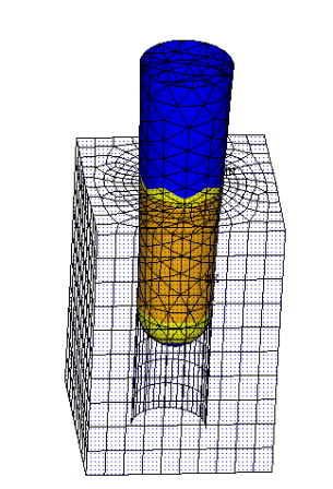
You can apply more than one geometry correction to the same contact or target surface. In the peg and slot example below, the peg is one contact surface. Two geometry corrections are applied to this contact surface: a revolute correction on the conical body and a spherical correction on the spherical tip. The cylindrical slot (target surface) requires only a revolute correction.
Figure 3.9: Geometry Correction Applied to Revolute and Spherical Surfaces
|
|
 |
| Original model configuration | Finite element model showing results |
This geometry correction technique assumes that the initial locations of the contact or target element corner nodes (but not necessarily the midside nodes of quadratic elements) lie on the true initial surface geometry. Geometry correction is most beneficial for small deflection analyses (small or large sliding).
When solving an interference fit problem, the shift direction may not follow the contact surface normal. In this case, you can use the SECTYPE and SECDATA commands to specify a user-defined contact surface normal:
SECTYPE,SECID,CONTACT,NORMAL ! SetType= CONTACT andSubtype= Normal for user-defined contact normal SECDATA,CSYS,NX,NY,NZ! Section data for user defined contact normal
| where |
CSYS = Number identifying the local coordinate system in which
the direction cosines are specified. If blank, it defaults to the global Cartesian
system. |
NX, NY,
NZ = Normal cosines of the shift direction with
respect to CSYS. |
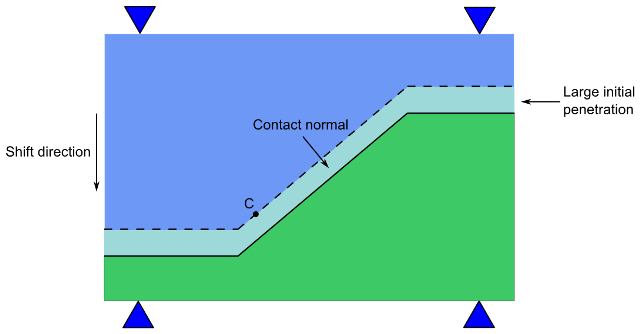
The figure below demonstrates a situation in which specifying a contact normal can improve convergence. By default, point C on the contact surface would follow the default contact normal direction. However, the convergence improves significantly if point C follows the user-defined contact surface normal (the shift direction) instead.
The user-defined contact surface normal is available for the following contact elements: CONTA172, CONTA174, and CONTA175. For more information, see Modeling Interference Fit.
When simulating bolts, detailed modeling of the bolt threads may not be practical since it requires a refined mesh discretization on both the bolt and the bolt hole in order to accurately model the thread geometry and achieve solution convergence. This detailed mesh discretization can also be computationally expensive. For system level modeling where the primary bolt function is to transfer a load, the thread detail is sometimes not necessary.
The bolt thread modeling technique available via the contact elements allows you to include the behavior of bolt threads without the added thread geometry and mesh discretization detail. Calculations are performed internally to approximate the behavior of the bolts. This feature offers simplified modeling with the near accuracy of a true threaded-bolt model. Bolt thread modeling is available for contact elements CONTA172, CONTA174, and CONTA175.
This technique can be applied to a 3D model or a 2D axisymmetric model. The mesh discretization of the threads is not needed. Instead, you model smooth cylindrical surfaces on both the bolt and the bolt hole geometries, which helps to ensure good quality element meshes. The contact normal is computed internally based on the user-specified thread geometry data and the two end points of the bolt axis. The following figure shows a bolt geometry with the primary parameters needed to define the thread.
Use the section commands SECTYPE and SECDATA to input the required data:
SECTYPE,SECID,CONTACT,BOLT
SECDATA,Dm,P,ALPHA,N,X1,Y1,Z1,X2,Y2,Z2
| where |
Dm = Pitch diameter, dm |
P = Pitch distance, p |
ALPHA = Half-thread angle, α |
N = Number of starts (defaults to 1) |
X1, Y1,
Z1, X2,
Y2, Z2 = Two end
points of the bolt axis in global Cartesian coordinates |
Use the SECNUM command to associate the contact elements with a particular section ID, or use the EMODIF command to assign a section ID to existing contact elements. Assign the section ID only to the contact elements on the thread region of the bolt geometry.
Either the bolt or bolt hole can be the contact surface. However, it is highly recommended that you apply the contact surface to the bolt and the target surface to the bolt hole.
Symmetric contact should not be used for bolt thread modeling. If symmetric contact is defined, the program will assume asymmetric contact and will usually select the bolt surface as the contact surface.
The value of the pitch diameter, dm, should be between the values of the major diameter (d) and the minor diameter (dr). See Figure 3.11: Bolt Thread Dimensions for details. If you only know the major diameter, you can input a rough estimation for the pitch diameter by using this equation:
dm = d - 0.65p
In order to achieve better accuracy, the mesh size over the thread region should be smaller than a quarter of the pitch distance, p. The half-thread angle, α, should be smaller than 90 degrees and larger than 0 degrees (α defaults to 30 degrees). The number of thread starts, n, defaults to 1 for a single-threaded bolt. Specify n = 2 for a double-threaded bolt. For a 3D contact model, input a positive half-thread angle for the right-hand thread and input a negative angle for the left-hand thread.
Either a general bolt-thread model or an unidirectional bolt-thread model can be defined. Input a positive pitch diameter dm for a general bolt thread model in which contact can occur on both side of the threads (the bolt is either in compression or in tension). Input a negative pitch diameter dm for the unidirectional bolt-thread model.
Specify X1, Y1, Z1 and X2, Y2, Z2 in Global Cartesian coordinates for the two end points of the axis of the bolt. For any 2D axisymmetric model, X1 = Z1 = X2 = Z2 = 0 must be specified. The order of the two end points is not important for the general bolt thread model. However, it must be chosen appropriately for the unidirectional bolt thread model. The vector (from the first point to the second point) should be oriented to point from the tip of the bolt to the head of the bolt if the bolt is in tension. The bolt axis should be flipped (that is, from the head to the tip) if the bolt is in compression. Contact may not be engaged if an incorrect bolt axis direction is specified. You should always check the stresses in the bolt to make sure that the contact surface is correctly constrained if the unidirectional bolt thread model is defined.
Keep the following points in mind when using this bolt thread modeling technique:
The diameter used for the mesh discretization of the bolt and nut bodies should follow the true geometry of the bolt-thread structure. In general, the solid model is based on the major diameter d, which is the diameter of the non-threaded surface.
The implementation of bolt thread modeling is based on a small strain formulation. The solution accuracy may be affected when the bolt rotates by a relatively large angle with respect to its original position.
This technique is valid only for standard straight threads. It is not applicable for nonstandard threads (such as tapered threads and buttress threads).
The maximum stress in the thread region may vary with mesh density. However, the overall stress distribution remains similar in pattern.
Using Gauss point as the location of contact detection (KEYOPT(4) = 0) is not recommended unless the mesh is sufficiently refined.
Using nodal point, normal to target, as the location of contact detection (KEYOPT(4) = 2) is not recommended.


