


REINF265
3D Smeared Reinforcing
REINF265 Element Description
The REINF265 3D smeared reinforcing element is available in two forms:
Structural/Thermal Smeared Reinforcing -- For extra reinforcing to 3D solid and shell elements
Special-Purpose Smeared Reinforcing -- For structural/thermal element embedding
3-D Structural/Thermal Smeared Reinforcing Element Description
For a structural reinforcing analysis, use REINF265 with standard 3D solid and shell elements (referred to as the base elements) to provide extra reinforcing to those elements. For a thermal reinforcing analysis, the supported base elements are thermal solids SOLID278 and SOLID279, and SOLID291.
The element uses a smeared approach and is suitable for modeling homogeneous thin structures or evenly spaced reinforcing fibers that appear in layered form. When used for modeling reinforcing fibers, each reinforcing layer contains a cluster of fibers with unique orientation, material, and cross-section area, and is simplified as a homogeneous membrane having unidirectional stiffness or conductivity. You can specify multiple layers of reinforcing in one REINF265 element. The nodal locations, degrees of freedom, and connectivity of the REINF265 element are identical to those of the base element.
For discrete reinforcing modeling options, see the documentation for the REINF264 element.
REINF265 has plasticity, stress-stiffening, creep, large-deflection, and large-strain capabilities.
For more information, see Reinforcing and Direct Element Embedding in the Structural Analysis Guide.
Figure 265.1: REINF265 Structural/Thermal Geometry
 3D 8-Node Solid or Solid Shell |
 3D 20-Node Solid |
 3D 10-Node Tetrahedral Solid |
 3D 4-Node Shell |


3D 8-Node Shell | |
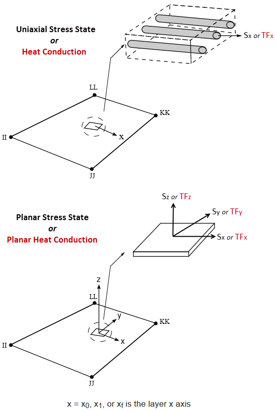
Figure 265.2: REINF265 Structural/Thermal Coordinate System
 |
 |
| Uniaxial Stress State | Plane Stress State |
|
X0 = Layer x axis if layer system LSYS and layer-orientation angle θ are not specified (default) Xc = Layer x axis if a local coordinate system for the layer is specified (SECDATA,,,KCN) Xf = Layer x axis if layer orientation angle θ
is specified
(SECDATA,,,, | |
REINF265 Structural/Thermal Input Data
The geometry and nodal locations for this element are shown in Figure 265.1: REINF265 Structural/Thermal Geometry. The REINF265 element and its base element share the same nodes and element connectivity.
You can easily create REINF265 elements from the selected base elements via the EREINF command. Section commands (SECTYPE and SECDATA) define the material ID, cross-section area, spacing, location, and orientation of reinforcing fibers. See Reinforcing and Direct Element Embedding in the Structural Analysis Guide for more information about creating REINF265 elements.
Each reinforcing layer can contain a cluster of fibers with unique orientation, material, and cross-section area, simplified as a homogeneous membrane having unidirectional stiffness.
The equivalent thickness h of the smeared reinforcing layer is given by:
h = A / S
where A is the cross-section area of a single fiber, and S is the distance between two adjacent fibers.
REINF265 can also be used to model homogeneous reinforcing membranes. The spacing input S is ignored and always set to 1.0 for reinforcing membranes. Therefore, the thickness h is equal to the cross-section area input A.
For a structural analysis, REINF265
supports a plane-stress or uniaxial-stress state
(SECCONTROL,,,MEMOPT). For a thermal analysis,
MEMOPT controls thermal conductivity KYY in the member
(individual reinforcing) coordinate system. If MEMOPT = 1, KYY = 0
and conduction is allowed only in the X direction. Select the plane-stress state for
homogeneous reinforcing membranes, and the uniaxial-stress state for clusters of reinforcing
fibers.
The coordinate systems for one reinforcing layer are shown in Figure 265.2: REINF265 Structural/Thermal Coordinate System. Each reinforcing layer is indicated by its intersection points (II, JJ, KK, LL for linear base elements, and II, JJ, KK, LL, MM, NN, OO, PP for quadratic base elements) with the base elements. Fibers in this layer are always parallel to the first coordinate axis x. The x axis is default to the first parametric direction S1 at the center of the layer. The default axis is defined as

where

|
| {x}II, {x}JJ, {x}KK, {x}LL = global nodal coordinates |
You can reorient the default layer coordinate system by projecting a local coordinate system (LOCAL) to the layer plane. One local coordinate system is allowed for each layer. The local coordinate system reference number is given via the SECDATA command.
You can further reorient the layer coordinate system by angle θ (in degrees) for each layer. The value of θ is also specified for each layer via the SECDATA command. For more information about visualizing fiber orientations, see /PSYMB.
For a structural analysis, REINF265
enables you to specify tension-only or compression-only reinforcing fiber behavior
(SECCONTROL,TENSKEY). This option is not
available when the plane-stress state is selected
(SECCONTROL,,,MEMOPT).
The element can account for redundant base element material where the
reinforcing fibers are located
(SECCONTROL,,REMBASE).
The element can account for transverse shear stiffness when using the plane-stress state with transverse shear stiffness (SECCONTROL,,,2). When solid base elements are used, the element can also account for bending stiffness (SECCONTROL,,,3).
For a structural analysis, REINF265 allows body-force-density element loading (BFE), as shown in these examples:
BFE,2,FORC,1, |
BFE,2,FORC,4, |
If applying body-force density to REINF265 elements (BFE), the program applies a uniform load to all members in the element. You can apply non-uniform body-force density to individual members via the mesh-independent method by loading to MESH200 elements.
Apply other structural element loading only to the base element. The temperature of the REINF265 element is identical to the temperature of the base element in a structural analysis.
For thermal reinforcing analysis, REINF265 allows heat-generation (HGEN) element loading (BFE), as shown in these examples:
BFE,2,HGEN,1, |
BFE,2,HGEN,5,%tab1%,,,, ! Member 2 of element 2 |
BFE,2,HGEN,9,%tab2%,,,, ! Member 3 of element 2 |
BFE,2,HGEN,13, |
VALUE1, VALUE2,
VALUE3, and VALUE4 are at the
corner points II JJ KK LL only. Midpoint values are not allowed. |
| If using the mesh-independent method for defining reinforcing, apply the HGEN load to the MESH200 elements instead. |
You can apply an initial state to this element in either of the following ways:
By applying an initial state directly on each REINF265 element (INISTATE).
By using the mesh-independent method for defining reinforcing to apply an initial state to MESH200 elements, enabling Mechanical APDL to transfer the initial state to the resulting reinforcing elements automatically. For more information, see Applying an Initial State to Reinforcing Elements in the Structural Analysis Guide.
A summary of the element input follows.
REINF265 Structural/Thermal Input Summary
- Nodes
Structural
Same as those of the base element, as shown:
Base Element REINF265 Nodes SOLID185 3D 8-Node Solid or SOLSH190 Solid Shell I,J,K,L,M,N,O,P SOLID186 3D 20-Node Solid I,J,K,L,M,N,O,P,Q,R,S,T,U,V,W,X,Y,Z,A,B SOLID187 3D 10-Node Tetrahedral Solid I,J,K,L,M,N,O,P,Q,R SHELL181 3D 4-Node Shell I,J,K,L SHELL281 3D 8-Node Shell I,J,K,L,M,N,O,P Thermal
- Degrees of Freedom
Structural
Same as those of the base element, as shown:
Base Element REINF265 Degrees of Freedom SOLID185 3D 8-Node Solid or SOLSH190 Solid Shell UX, UY, UZ SOLID186 3D 20-Node Solid UX, UY, UZ SOLID187 3D 10-Node Tetrahedral Solid UX, UY, UZ SHELL181 3D 4-Node Shell UX, UY, UZ, ROTX, ROTY, ROTZ SOLSH190 3D 8-Node Shell UX, UY, UZ, ROTX, ROTY, ROTZ Thermal
- Real Constants
None - Material Properties
TB command: See Element Support for Material Models for this element. MP command: EX, (PRXY or NUXY), ALPX (or CTEX or THSX), DENS, GXY, ALPD, BETD, DMPR, DMPS, CP, KXX, KYY - Surface Loads
None - Body Loads
- Temperatures (Structural) --
Same as those of the base element
- Body-Force Density --
Standard method -- Specified via BFE
Mesh-independent method -- Specified via BFE on MESH200 elements
- Thermal --
HGEN –
- Special Features
REINF265 Structural/Thermal Output Data
The solution output associated with the element is in two forms:
Nodal displacements included in the overall nodal solution
Additional element output as shown in Table 265.1: REINF265 Element Output Definitions – Structural Analysis.
The following figure illustrates the axial stress component:
Unlike layered solid or shell elements (such as SHELL181), REINF265 always outputs the element solution for all reinforcing layers. You can select solution items for a specific reinforcing layer (LAYER) for listing and visualization by using full graphics (/GRAPHICS,FULL). Visualization via PowerGraphics (/GRAPHICS,POWER) is not affected by the LAYER command; all reinforcing layers are displayed simultaneously. See the Basic Analysis Guide for ways to review results.
REINF265 element solution is always output in the layer coordinate system and does not support transformation to a different coordinate system. RSYS has no effect on REINF265 element solution.
To inspect REINF265 element results, select only REINF265 element results or adjust translucency level of the base elements before executing any plotting command. REINF265 display options are also available directly via the GUI ().
The Element Output Definitions table uses the following notation:
A colon (:) in the Name column indicates that the item can be accessed by the Component Name method (ETABLE, ESOL). The O column indicates the availability of the items in the file jobname.out. The R column indicates the availability of the items in the results file.
In either the O or R columns, “Y” indicates that the item is always available, a letter or number refers to a table footnote that describes when the item is conditionally available, and “-” indicates that the item is not available.
Table 265.1: REINF265 Element Output Definitions – Structural Analysis
| Name | Definition | O | R |
|---|---|---|---|
| EL | Element number and name | - | Y |
| NODES | Nodes (as shown in "REINF265 Structural/Thermal Input Summary") | - | Y |
| MAT | Material number | - | Y |
| THICK |
Averaged equivalent layer thickness (uniaxial stress state) Averaged layer thickness (plane stress state) | - | Y |
| SPACING | Averaged distance between two adjacent fibers [5] | - | Y |
| VOLU: | Volume | - | Y |
| XC, YC, ZC | Center location | - | 3 |
| TEMP |
T1, T2, T3, T4 for reinforcing layer 1; T5, T6, T7, T8 for reinforcing layer 2; ending with temperatures for the last reinforcing layer NL (4*NL maximum) | - | Y |
| S:x | Axial stresses (uniaxial-stress state) | 2 | Y |
| S:x, y, z, xy, yz, xz | Stresses (plane-stress state, Sz = 0.0) | 2 | Y |
| EPEL:x | Axial elastic strains (uniaxial-stress state) | 2 | Y |
| EPEL:x, y, z, xy, yz, xz | Elastic strains (plane-stress state) | 2 | Y |
| EPTH:x | Axial thermal strains (uniaxial-stress state) | 2 | Y |
| EPTH:x, y, z, xy | Thermal strains (plane-stress state) | 2 | Y |
| EPPL:x | Axial plastic strains (uniaxial-stress state) | 2 | 1 |
| EPPL:x, y, z, xy, yz, xz | Plastic strains (plane-stress state) | 2 | 1 |
| EPCR:x | Axial creep strains (uniaxial-stress state) | 2 | 1 |
| EPCR:x, y, z, xy, yz, xz | Creep strains (plane-stress state) | 2 | 1 |
| EPTO:x | Total axial mechanical strains (EPEL + EPPL + EPCR, uniaxial-stress state) | Y | - |
| EPTO:x, y, z, xy, yz, xz | Total mechanical strains (EPEL + EPPL + EPCR, plane-stress state) | Y | - |
| EPTT:x | Total axial strains (EPEL + EPPL + EPCR + EPTH, uniaxial-stress state) | Y | - |
| EPTTx, y, z, xy, yz, xz | Total strains (EPEL + EPPL + EPCR + EPTH, plane-stress state) | Y | - |
| NL:EPEQ | Accumulated equivalent plastic strain | - | 1 |
| NL:CREQ | Accumulated equivalent creep strain | - | 1 |
| NL:SRAT | Plastic yielding (1 = actively yielding, 0 = not yielding) | - | 1 |
| NL:PLWK | Plastic work/volume | - | 1 |
| N11 | Averaged axial force per unit length [5] | - | Y |
| LOCI:X, Y, Z | Integration point locations | - | 4 |
Table 265.2: REINF265 Element Output Definitions – Thermal Analysis
| Name | Definition | O | R |
|---|---|---|---|
| EL | Element number and name | 2 | Y |
| NODES | Nodes (as shown in "REINF265 Structural/Thermal Input Summary") | 2 | Y |
| MAT | Material number | 2 | Y |
| THICK |
Averaged equivalent layer thickness (uniaxial stress state) Averaged layer thickness (plane stress state) | - | Y |
| VOLU: | Volume | 2 | Y |
| XC, YC, ZC | Center location | - | 3 |
| BFE TEMP |
T1, T2, T3, T4 for reinforcing members [6] | - | Y |
| TG:x y | Temperature gradient along the x and y directions (of layer CSYS) for all members [6] | 2 | |
| TF:x y | Heat flux along the x and y directions (of layer CSYS) for all members [6] | 2 | |
| LOCI:X, Y, Z | Integration point locations | - | 4 |
Nonlinear solution output if the element has a nonlinear material.
For structural analysis, stresses, total strains, plastic strains, elastic strains, creep strains, and thermal strains in the element coordinate system are available for output. Transverse-shear terms (yz, xz) are available when SECCONTROL,,,2 is issued. The structural output values are available on both top and bottom surfaces of a layer when bending stiffness is included (SECCONTROL,,,3). For thermal analysis, temperature gradients and heat flux in the element coordinate system are available for output.
Available only at centroid as a *GET item.
Available only if OUTRES,LOCI is used.
Table 265.3: REINF265 Structural/Thermal Item and Sequence Numbers lists output available through ETABLE using the Sequence Number method. See Creating an Element Table and The Item and Sequence Number Table in this document for more information. The following notation is used in Table 265.3: REINF265 Structural/Thermal Item and Sequence Numbers:
- Name
output quantity as defined in Table 265.1: REINF265 Element Output Definitions – Structural Analysis
- Item
predetermined Item label for ETABLE
- E
sequence number for single-valued or constant element data
The i value (where i = 1, 2, 3, ...,
NL) represents the reinforcing member number of the element.
NL is the maximum reinforcing member number (1 
NL
 250).
250).
REINF265 Structural/Thermal Assumptions and Restrictions
Zero-volume elements are invalid.
A valid base element must be present for each REINF265 element.
The reinforcing element is firmly attached to its base element. No relative movement between the reinforcing element and the base is allowed. For a thermal analysis, the temperature field is continuous at the interface between the base element and the reinforcing.
Through-thickness reinforcing is not allowed in shells and layered solid elements.
Stress stiffening is always included in geometrically nonlinear analyses (NLGEOM,ON). You can activate prestress effects via the PSTRES command.
To simulate tension-/compression-only reinforcing fibers, a nonlinear iterative solution approach is necessary.
Linear tetrahedral base elements (degenerated SOLID185 and SOLID285) have constant stress/strain in the element and are therefore not applicable to REINF265 bending stiffness (SECCONTROL,,,3).
REINF265 Structural/Thermal Product Restrictions
No product-specific restrictions exist for this element.

3-D Special-Purpose Smeared Reinforcing Element Description
REINF265 can represent the interior intersection areas between embedded elements (elements completely or partially enclosed within other elements) and the base elements (elements surrounding the embedded elements). These special-purpose reinforcing elements capture the bonding stiffness between the embedded and base elements. However, they do not introduce additional structural stiffness, mass, and external forces in structural analyses, nor do they introduce additional conduction, damping, and external heat in a thermal analysis.
REINF265 special-purpose elements are generated via EEMBED.
In this figure, black lines and dots indicate a base element, blue lines and dots indicate an embedded beam element, and red lines indicate the interior intersection area represented by a REINF265 special-purpose element:
Figure 265.4: REINF265 Special-Purpose Geometry
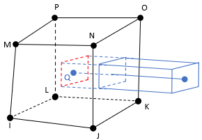 3D 2-Node Beam with RECT section embedded in 3D 8-Node Solid | 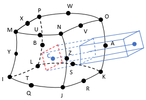 3D 2-Node Beam with RECT section embedded in 3D 20-Node Solid |
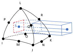 3D 2-Node Beam with RECT section embedded in 3D 10-Node Solid |
For more information, see Direct-Embedding Workflow in the Structural Analysis Guide.
REINF265 Special-Purpose Input Summary
- Nodes
Structural
Include nodes of the base element and a node (at which location the REINF265 elements are generated) of the embedded element:
Base Element REINF265 Nodes SOLID185 3D 8-Node Solid I,J,K,L,M,N,O,P,Q SOLID186 3D 20-Node Solid I,J,K,L,M,N,O,P,Q,R,S,T,U,V,W,X,Y,Z,A,B,C SOLID187 3D 10-Node Tetrahedral Solid I,J,K,L,M,N,O,P,Q,R,S Thermal
Include nodes of the base element and a node (at which location the REINF265 elements are generated) of the embedded element:
Base Element REINF265 Nodes SOLID278 3D 8-Node Thermal Solid (KEYOPT(3) = 0) I,J,K,L,M,N,O,P,Q SOLID279 3D 20-Node Thermal Solid (KEYOPT(3) = 0) I,J,K,L,M,N,O,P,Q,R,S,T,U,V,W,X,Y,Z,A,B,C SOLID291 3D 10-Node Tetrahedral Thermal Solid I,J,K,L,M,N,O,P,Q,R,S Coupled-Field
Include nodes of the base element and a node (at which location the REINF265 elements are generated) of the embedded element:
Base Element REINF265 Nodes SOLID225 3D 8-Node Coupled-Field Solid (KEYOPT(1) = 11, 110, or 111) I,J,K,L,M,N,O,P,Q SOLID226 3D 20-Node Coupled-Field Solid (KEYOPT(1) = 11, 110, or 111) I,J,K,L,M,N,O,P,Q,R,S,T,U,V,W,X,Y,Z,A,B,C SOLID227 3D 10-Node Coupled-Field Solid (KEYOPT(1) = 11, 110, or 111) I,J,K,L,M,N,O,P,Q,R,S - Degrees of Freedom
Structural
Same as those of the embedded element, as shown:
Embedded Element REINF265 DOFs LINK180 3-D Spar UX, UY, UZ BEAM188 3-D 2-Node Beam UX, UY, UZ, ROTX, ROTY, ROTZ BEAM189 3-D 3-Node Beam UX, UY, UZ, ROTX, ROTY, ROTZ Thermal
Base Element REINF265 Nodes SOLID278 3D 8-Node Thermal Solid (KEYOPT(3) = 0) TEMP SOLID279 3D 20-Node Thermal Solid (KEYOPT(3) = 0) TEMP SOLID291 3D 10-Node Tetrahedral Thermal Solid TEMP Coupled-Field
Supported combinations of common degrees of freedom between embedded and base elements are listed in Supported Elements for Direct Embedding in the Structural Analysis Guide.
- Sections
- Real Constants
None - Material Properties
None - Surface Loads
None - Body Loads
None
REINF265 Special-Purpose Output Data
REINF265 elements generated via EEMBED have no solution output except nodal displacements (for structural analysis) or temperature (for thermal analysis).