


The Display tab contains options for moving your model within the Geometry window as well as a variety of display-based options such as wireframe, edge thickness, ply directions, etc.

This tab contains the following Groups.
Orient
The Orient group provides model orientation options.

Options for this group include:
| Option | Description |
|---|---|
| Isometric | Reorients your model into the isometric view. This option also includes the
following drop-down menu options:
|
| Look At | Centers your model in the Geometry window based in the currently selected face or plane. |
| Views | Provides a drop-down menu of options that enable you to change the viewpoint (front, back, right, etc.) of your model as well as an option to orient your model in the isometric view. |
| Previous/Next | Scrolls forward or backward from the last view displayed in the Geometry window. |
| Rotate ± X/Y/Z | Rotates your model in the Geometry window about the axis. |
| Pan Up/Down/Right/Left | Pans your model in the Geometry window. |
| Zoom In/Out | Zooms in or out of your model. |
Annotation
The Annotation group enables you to make changes to how Annotations are displayed in the Geometry window as well as specify preferences.

Options for this group include:
| Option | Description |
|---|---|
| Random | By default, the annotations for objects types (loads, supports, named selections, etc.) are shown by a unique color. That is, all loads are red and all supports are blue etc. Selecting the option, you change the colors used for annotations. |
| Rescale | Changes the size of annotation symbols, such as load direction arrows. |
| Preferences | Displays the Preferences dialog that you use to set preferences for the display of annotations. |
Style
The Style group provides model display options such as wireframe, showing the mesh, etc.

Options for this group include:
| Option | Description |
|---|---|
|
Display |
Provides a drop-down menu of the following model display options:
|
|
Show Mesh |
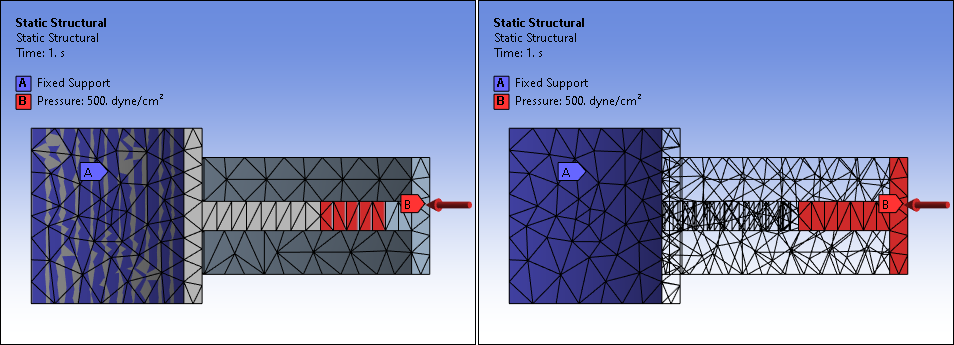
Displays your model's mesh regardless of the selected Outline object. When enabled, to make sure that Annotations display properly, also turn on Wireframe mode. See the related Note below. |
|
Thick Shells and Beams |
Displays the thickness of shells, beams, and particles, when viewing mesh or results. By default, this option is inactive. Review the Note below for additional display characteristics associated with this feature. |
|
Cross Section |
Displays line body cross sections as 3D geometry. See Viewing Line Body Cross Sections for details. |
|
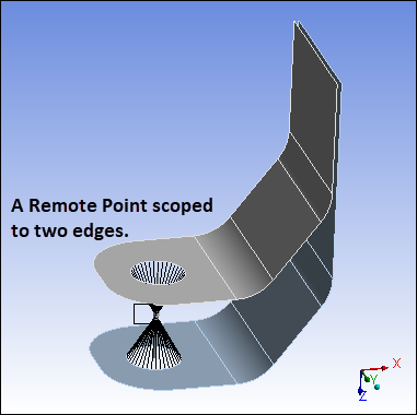
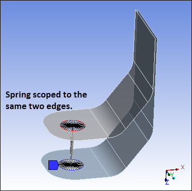
Remote Point Connections |
Displays connection lines between geometry and Remote Points or between supported remote boundary conditions and Remote Points. See the example below. Once you have generated the mesh, the connection lines are drawn between the Remote Point and the nodes on the corresponding mesh of the underlying geometry or boundary condition. Important: Only the nodes that are contained inside of the Pinball Radius property setting are displayed. |
|
Display Style |
Provides a drop-down menu with options to display the parts and bodies of your model based on the available styles. For example, if an assembly is made of parts of different materials, you can color the parts based on the material. That is, all structural steel parts have the same color, all aluminum parts have the same color and so on. See the Color Coding of Parts topic. |
Remote Point Connections Display Example
 |
 |
Note: As illustrated below, annotations may not always display properly when the option is activated. Turning on Wireframe mode accurately displays Annotations when is selected.
Note:
Displaying Shells for Large Deflections: The display of shells may become distorted for large deformations such as in large deflection or during an Explicit Dynamics analysis. A workaround for this is to disable Shell Thickness by toggling the Thick Shells and Beams option. Or, set a variable, UsePseudoShellDisp = 1, using the option from the File tab. It may be necessary to toggle the deformation scaling from True Scale to Undeformed to True Scale again (see Scaling Deformed Shape in the Context Tabs section). Note that this option requires True Scaling to work properly.
Displaying Shells with Thickness on Geometry that Spans Large Angles: The graphical representation of your meshed shell model may appear distorted when the shell spans a large angle, such as a 90° angle. Ordinarily, the application calculates an average of the normals between elements (based on a default setting of 180°). Given too large of an angle, a graphical abnormality may occur. Modify the default setting using the Graphics option in the Options dialog box.
60°is the recommended setting to avoid the display of any graphical abnormalities.Displaying Results on Very Thin Shell Bodies: If you are viewing result contours of a very thin geometry, you could observe a graphical distortion as a result of colors from the back face of the geometry bleeding onto the front face of the geometry. This is a graphics-based limitation. In addition, turning off the Thick Shells and Beams option can cause the distortion to worsen.
Displaying Shells on Shared Entities: The display of shells is done on a nodal basis. Therefore, graphics plot only 1 thickness per node, although node thickness can be prescribed and solved on a per elemental basis. When viewing shell thickness at sharp face intersections or a shared body boundary, the graphics display may become distorted.
Shell Element Display from Mesh Changes. If you employ a feature that changes the model’s mesh, such as the Nonlinear Adaptive Region or Fracture, you may see display errors for expanded shell elements as a result of the changing mesh. Disable the Thick Shells and Beams option to properly display the elements.
Displaying Contours and Displaced Shapes on Line Bodies: The contour result on a line body are expanded to be viewed on the cross section shape, but only one actual result exists at any given node and as a result no contour variations across a beam section occur.
Display Pipes using Pipe Idealizations: Although the solution will account for cross section distortions, the graphics rendering for the results display the cross sections in their original shape.
Vertex
The Vertex group provides vertex display options.

Options for this group include:
| Option | Description |
|---|---|
| Show Vertices | Highlights all vertices on the model. This feature is especially useful when examining complex assemblies where vertices might normally be hidden from view. It can also be used to ensure that edges are complete and not segmented unintentionally. |
| Close Vertices |
Displays tightly clustered vertices on your model. This vertex display feature has an accompanying scale menu. When you select this option, a corresponding scale menu also activates and includes application generated tolerances as well as an option that enables you to enter a tolerance value. The application calculates the default tolerance (). This value is 0.1% of the diagonal measurement of your model's Bounding Box dimensions. Additional system options are factors of this base measurement and you can manually enter a tolerance using the option. The cannot exceed 5% of the model's Bounding Box dimensions. Based on the selected tolerance, the application highlights pairs of vertices that are closer to one another than the specified tolerance and draws segments between the vertices to further illustrate proximity. |
Edge
The Edge group provides display options used to display the edges on your model, their connectivity, and how they are shared by faces. Also see the Preparing Assemblies of Surface Bodies section for more information.

Options for this group include:
| Option | Description |
|---|---|
| Direction | Displays model edge directions. The direction arrow appears at the midpoint of the edge. The size of the arrow is proportional to the edge length. |
| Mesh Connection | Displays the edges using coloring schema, by taking into account the mesh connection information. |
| Thicken | This option increases the thickness of the edges displayed on your model. If you also have the Display Mesh option active, the application only thickens the lines of annotations (the scoped edges) for an object scoped to edges. For example, annotations for the scoping of a boundary condition, Named Selection, result, etc. |
| Color | The options of this drop-down menu highlight the edges of your model using
specific colors. Options include:
|
| Free (edge display) | Displays drop-down menu with the following options:
|
| Single (edge display) | Displays drop-down menu with the following options:
|
| Double (edge display) | Displays drop-down menu with the following options:
|
| Triple (edge display) | Displays drop-down menu with the following options:
|
| Multiple (edge display) | Displays drop-down menu with the following options:
|
Note: Note the following restrictions when you are using the Edge options on the mesh, as compared to their use on geometry:
When you are using the Edge Coloring options when viewing the mesh, the application only draws the corner nodes to display the outline of the elements (mid-side nodes are ignored if available). You can use the Wireframe tool and also hide bodies to properly display the colored edges. And in doing so, you can see where mid-side nodes are located, if available.
Not all of the buttons/options are functional, for example, Double always displays thin black lines. The width of the colored lines cannot be changed. They are always thick.
During slicing, the colors of shared element edges are not drawn. They display as black and appear only when the selected section plane is losing focus in the slice tool pane.
Explode
The Explode group is a graphical display feature used to create imaginary distance between geometry bodies (only) of your model for viewing purposes.

Once the mesh is generated, this feature is not supported when you have the Mesh object selected or when the Show Mesh feature is turned on. In addition, when viewing the mesh, exploded geometry bodies, although not visible in the Geometry window, are still in an exploded state and passing the cursor over an exploded body will highlight the (otherwise invisible) body and it is also selectable at this time.
- Reset Button
This button reassembles the parts of your model to their original position.
- Explode View Factor Slider
This slider tool enables you to change the exploded distance between the parts from their original position.
- Move Springs/Beams with Parts
The button
 for this option
enables you to see an accurate representation of connections on your model, such as
Springs and Beams, by showing the connections stretched from the assigned locations on
the moving parts. Because the display is graphically accurate, the processing
requirements are intensive. Use the default position (not active/depressed) when
moving the slider for large models and when connection representations are not
critical.
for this option
enables you to see an accurate representation of connections on your model, such as
Springs and Beams, by showing the connections stretched from the assigned locations on
the moving parts. Because the display is graphically accurate, the processing
requirements are intensive. Use the default position (not active/depressed) when
moving the slider for large models and when connection representations are not
critical.- Assembly Center Drop-Down List
This drop-down list provides the available coordinate system options as well as the option (default setting) that defines the position in space from which the exploded view originates and the Assembly Center (Visible) option that accounts for the visible parts only. The is always an available option as well as any user-defined coordinate systems.
Note: The explode view feature does not support the Body Views display, such as when you are displaying contact bodies in separate windows.
Viewports
The Viewports group enables you to split the Geometry window into multiple windows, synchronize the windows as desired, and/or capture an image of the currently displayed viewports. See the Using Viewports section for more information.

Display
The Display group contains the Show drop-down menu that provides several general display options, such as the ruler and legend.

Options of the menu include:
| Option | Description |
|---|---|
| Turns the Geometry window ruler on and off. | |
| Turns the Geometry window legend on and off. | |
| Turns the Geometry window triad on and off. | |
| Displays the model's mesh. | |
| Displays all the available coordinate systems defined on the model – default as well as user defined. | |
| Toggles the visibility of either a single cyclic sector mesh or the full symmetry mesh in a cyclic symmetry analysis. Toggling this option can help preview before solving the density of nodes on the sector boundaries, or it can help confirm the expanded mesh in each case. | |
| Erodes Nodes | Turns the visibility of eroded nodes for explicit dynamics analyses on or off. |
Displays a drop-down menu with options to change how faces are displayed as a
function of back-face culling. Options include:
|