The Graphics toolbar sets the selection/manipulation mode for the cursor in the Geometry window. The toolbar also provides commands for modifying a selection or for modifying the viewpoint. You can turn this toolbar on and off using the option in the Manage option's drop-down menu located in the Layout group on the Home tab.
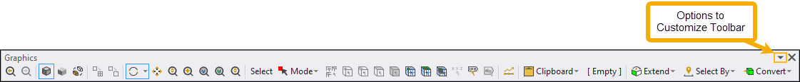
You can add or remove options from this toolbar using the Customization Menu shown below. You access this menu using the down-arrow drop-down menu at the far end of the toolbar.
| Customization Menu | Option | Description |
|---|---|---|
|

| Previous/Next |
To return to the last view displayed in the Geometry window, click the Previous View button on the toolbar. By continuously clicking you can see the previous views in consecutive order. After displaying previous views in the Geometry window, click the Next View button on the toolbar to scroll forward to the original view. |
| Shaded Exteriors and Edges | Displays the model in the Geometry window with shaded exteriors and distinct edges. This option cannot be used in combination with either the Shaded Exterior or Wireframe views. | |
| Shaded Exteriors | Displays the model in the Geometry window with shaded exteriors only. This option cannot be used in combination with either the Shaded Exterior and Edges or Wireframe views. | |
| Wireframe | Enable the display mode. The model displays in
the Geometry window with a wireframe display rather than a shaded (recommended for
seeing gaps in surface bodies) display. The Wireframe option not only applies to
geometry, mesh, or named selections displayed as a mesh, but extends to probes,
results, and variable loads to enable a better understanding of regions of interest.
When set, just the exterior faces of the meshed models are shown, not the interior
elements. Selecting any of the edges options
on contour results automatically closes Wireframe mode. Note: When active, green scoping is not drawn on probes. Also, elements are shown on probes and results, whereas the outline of the mesh is shown on isoline contour results. | |
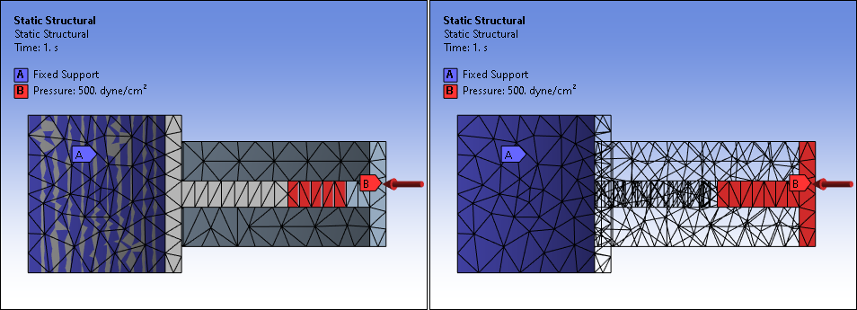
| Show Mesh | Display the model's mesh. Enabling this option displays the model’s mesh regardless of the selected tree object. When enabled, to make sure that Annotations display properly, also turn on Wireframe mode. See Note below. | |
| Rotate | Activates the model Rotate feature. Free rotation is the default behavior. Also
see the Manipulating the Model in the Geometry
Window section. Note: This button offers a drop-down menu to switch between free and axis-based rotation. Switching between these menu options also defines the default behavior in the Options dialog. | |
| Pan | Reposition your model laterally and vertically in the Geometry window. | |
| Zoom | Displays a closer view of the body by dragging the mouse cursor vertically toward
the top of the Geometry window, or displays a more distant view of the body by
dragging the mouse cursor vertically toward the bottom of the Geometry window. Note: If you zoom in on a model at an extreme factor (over 105), you may see the graphical display of geometry edges or mesh element edges appear distorted. These display distortions are due to the limitations of the computer’s architecture (precision of storing data) and the display screen resolution. | |
| Zoom To Fit | Fit the entire model in the Geometry window. | |
| Zoom To Selection | Zoom in on the currently selected item in the Geometry window. | |
| Toggle Magnifier Window On/Off | Displays a Magnifier Window, which is a shaded box that functions as a magnifying
glass, enabling you to zoom in on portions of the model. When you toggle the Magnifier
Window on, you can:
| |
| Select | Label only. | |
| Mode |
Display a drop-down menu of options that define how geometry, node, or element selections are made:
These options are used in conjunction with the selection filters (Vertex, Edge, Face, Body, Node, Element) Note: Selection shortcuts:
| |
| Smart Select | For mode, use this option to select or highlight vertices, edges, and faces on the model without needing to specify a selection filter (Vertex, Edge, or Face). Use the [Ctrl] key or hold down the left-mouse button to select multiple entities. When you make a selection, an icon displays that enables you to select the parent body for the current selection(s). This option supports the , , and Mini Selection Toolbar features. This option does not currently support depth picking. | |
| Vertex | Activate Vertex geometry selection option. | |
| Edge | Activate Edge geometry selection option. | |
| Face | Activate Face geometry selection option. | |
| Body | Activate Body geometry selection option. | |
| Node | Activate Node mesh selection option. | |
| Element Face | Activate Element Face mesh selection option. | |
| Element | Activate Element mesh selection option. | |
| Hit Point Coordinate | Available only if you are setting a location, for example, a local coordinate
system. This option enables the exterior coordinates of the model to display adjacent
to the cursor and updates the coordinate display as the cursor is moved across the
model. If you click with the cursor on the model, a label displays the coordinates of
that location. This feature is functional on faces only. It is not functional on edges
or line bodies. Note: You can change the default display settings for the font (size, style, color) used with this feature by changing the settings of the Probe Tool and Hit Point Coordinate preference in the Graphics category of the Options dialog. | |
| Label | Select and drag and drop an annotation label anywhere on the corresponding scoping. Not all objects support this option. | |
| Imported Data Highlight | For certain data imported through the External Model system, this option enables you to highlight the graphical representation of the data in the Geometry window. This option behaves just like you were selecting a row in the Worksheet for the imported data. See the User Interface Options topic in the Importing Mesh-Based Databases section for more information. | |
| Direction | Chooses a direction by selecting a single face, two vertices, or a single edge (enabled only when Direction field in the Details view has focus). See Pointer Modes. | |
| All | Select all geometric entities of your model based on the current selection filter type (vertex, edge, face, or body). Ctrl+A also performs this action. | |
| Invert | Automatically select entities of the same type (face, edge, etc.) that are not currently selected. Any selection made before selecting this option is removed. | |
| Display Graph | Display the content of the Graph window in the Geometry window. | |
| Clipboard Information | To help you keep track of what is contained in the Clipboard, once you make selections (or add or change) the Clipboard menu displays the current number of entities contained in the Clipboard, such as 1 Body, as illustrated above. When no selections are contained in the Clipboard, this field contains the text string "Empty." Also note that the status bar displays active Geometry window selections. | |
| Extend | Adds adjacent faces (or edges) within angle tolerance, to the currently selected face (or edge) set, or adds tangent faces (or edges) within angle tolerance, to the currently selected face (or edge) set. See the Extend Selection Menu topic for additional information about these options. | |
| Select By | Display a drop-down menu of selection options. See the Select group topic in the Selection Tab section for more information. | |
| Convert | Display a drop-down menu of options to change your currently selected geometric entity or mesh item to a different geometric entity or mesh item. See the Convert To group topic in the Selection Tab section for more information. | |
| Viewports | Split the Geometry window into multiple windows. | |
| Sync Viewports | Synchronize the Viewports display in each window to reorient/move (pan, zoom, rotate) your model in each window simultaneously. | |
| Front/Back/Right/Left/Top/Bottom | These options reorient the display of your model. | |
| Accelerated Display | Improve the display time for mesh and result objects. | |
| Reset Toolbar | Reset the Graphics Toolbar to the default display configuration. |
Note: As illustrated below, annotations may not always display properly when the option is activated. Turning on Wireframe mode accurately displays annotations when is selected.