


Defines a distinct location in your simulation domain for which you define the type of physics that will be solved.
Acoustic Analyses
During an acoustic analysis, an Acoustics Region and/or a Structural Region object are automatically included in the Outline. Both of these objects are Physics Region objects. You use them to specify the geometry bodies that belong to the Structural or Acoustics physics type. All of the bodies must have a physics type associated via Physics Region objects.
Coupled Field Analyses
During a Coupled Field analysis, a Physics Region object is automatically included in the Outline. You use this object to specify the geometry bodies that belong to the Structural, Acoustics, Electric, Thermal or some supported combination of these types. All of the bodies must have a physics type specified by a Physics Region object.
Note: The Show Coupled Physics Analysis setting, available in the Graphics category of the preferences dialog, enables you to display the bodies and/or parts associated with each properly defined Physics Region as a different color when the Environment object is selected.
|
Acoustics and Structural Region objects for a Static Acoustics analysis: 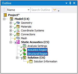 | |
|
Physics Region object for a Coupled Field Static analysis: 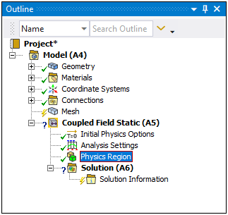
|
Object Properties
The Details Pane for this object includes the following properties.
| Category | Properties/Options/Descriptions | ||||||||||||||
|---|---|---|---|---|---|---|---|---|---|---|---|---|---|---|---|
|
Scope |
Scoping method: Specify as Geometry Selection (default) or Named Selection.
| ||||||||||||||
|
Definition |
Structural: Specify the selected geometry or geometries as Structural. The default setting depends upon the analysis type. Acoustics: Specify the selected geometry or geometries (solid bodies only) as Acoustic. The default setting depends upon the analysis type. Thermal: Specify the selected geometry or geometries (solid bodies only) as Thermal for a coupled field analysis. The default setting is . Electric: Options include , , and . Specify the selected geometry or geometries as Electric. This property also specifies the formulation type, whether it is a charge-based formulation or current-based formulation. The default setting depends upon the analysis type. Suppressed: Toggles suppression of the object. The default setting is . | ||||||||||||||
|
Coupling Options (Coupled Field Analyses Only) |
Thermal Strain: This property is visible when the Thermal and Structural properties above are set to . You use this property to specify the coupling method for a structural-thermal physics problem. Options include (default), , and . The setting of the option varies based on the selected physics as well as the selected solver.
Thermoelastic Damping: This property is visible for a Coupled Field Transient analysis when the Thermal and Structural properties above are set to . Options include and (default). Piezoelectric: When the Structural property is set to and the Electric property is set to , this read-only property indicates that the selected region is a piezoelectric region. If the material assignment of any body scoped to the Physics Region includes a piezoelectric matrix, defined in the Engineering Data workspace, this property is activated and automatically set to . Otherwise, it is set to . Electrostatic Force: For a Coupled Field Static and Coupled Field Transient analyses when the Structural property is set to and the Electric property is set to , this property indicates that the selected region includes electrostatic structural coupling defined. It applies an electrostatic force to the scoped bodies based on the following options:
Note: These options are also available for static coupling when applied as an upstream system for a prestressed Coupled Field Harmonic analysis. | ||||||||||||||
|
Acoustic Domain Definition (Visible for Acoustic Definition Only) |
Artificially Matched Layers: Options include (default), , and . When you select or , a new PML Options category displays in the details view that enable you to define the PML options, as described below. Important: For a Static Acoustics analysis, if you activate this property, downstream Modal systems become invalid.
For additional information, see the Artificially Matched Layers section in the Mechanical APDL Acoustic Analysis Guide. Element Morphing: Enables you to specify that the mesh for the bodies selected by the Acoustics Region can be updated, that is, morphed, due to any deflection of the Structural Region. Options include (default), , and . The setting specifies the mesh of the selected bodies is morphed and when , the setting considers the following:
Note: Acoustic elements do not affect a Static Acoustics analysis other than for a morphed mesh.
| ||||||||||||||
|
Piezoelectric Domain Definition (Visible for Piezoelectric Coupling in Coupled Field Harmonic analyses) |
Perfectly Matched Layers: Options include (default) and . When you select , and Options category displays in the Details that enables you to define the PML Options properties, as described below. | ||||||||||||||
|
Structural Domain Definition (Visible only when the Structural physics property set to in Coupled Field Harmonic analysis) |
Perfectly Matched Layers: Options include (default) and . When you select , and Options category displays in the Details that enables you to define the PML Options properties, as described below. | ||||||||||||||
|
PML Options (Visible when Artificially Matched Layers or Perfectly Matched Layers property is set to PML) |
PML Element Coordinate System: The Global Coordinate System is the default setting. PML Options: Options include (default) and . Reflection Coefficients: Options include (default) and . When this property is set to , the following additional properties display based upon the setting of the PML Options property, either:
Evanescent Wave Attenuation: Options include (default) and . For additional information, see the Perfectly Matched Layers (PML) section in the Mechanical APDL Acoustic Analysis Guide. | ||||||||||||||
|
(Visible for Acoustic analyses when Artificially Matched Layers property set to ) |
Reflection Coefficients Evanescent Wave Attenuation: Options include (default) and . For additional information, see the Irregular Perfectly Matched Layers (IPML) section in the Mechanical APDL Acoustic Analysis Guide. | ||||||||||||||
|
Advanced (Visible for Acoustic Definition Only) |
Reference Pressure: Enter a Reference Pressure value. The
default value is Reference Static Pressure: Enter a Reference Static Pressure
value. The default value is Fluid Behavior: Specify the compressibility of the fluid. Available options are (default) or . |
Tree Dependencies
Valid Parent Tree Object: The Environment object is the only valid parent object.
Valid Child Tree Objects: No current child objects are supported for this object.
Insertion Methods
This object is automatically inserted into the Outline when you open the analysis type in Mechanical. Additional objects can be inserted. Select the analysis's environment object, and:
Right-mouse click and select > .
Or...
Select the option on the Evironment Context tab.
Right-click Options
In addition to common right-click options, relevant right-click options for this object include:
>
[Various loads and supports. See Load Type Boundary Conditions]
Note: For more detailed information about setting the Acoustic Domain Definition and Acoustic FSI Definition, see the Elements for Acoustic Analysis section of the Mechanical APDL Element Reference.
API Reference
See the Physics Region section of the ACT API Reference Guide for specific scripting information.
Additional Related Information
For more information on acoustic domain definition and FSI definition properties, refer to Elements for Acoustic Analysis section in the Mechanical APDL Element Reference