Once you have generated the mesh on your model, you can select one or more elements or element faces on your mesh using the Element or Element Face selection filter on the Graphics Toolbar as well as the options of the Select Mode drop-down menu. The following topics describe element-based selection methods and features:
Selecting Elements or Element Faces
To select elements/element faces:
Generate the mesh by highlighting the Mesh object and clicking the Generate Mesh button.
From the Graphics Toolbar, select the or filter option.
As needed, choose the desired selection tool from the drop-down menu on the Graphics Toolbar.
Select an individual element or multiple elements. To select multiple elements:
Hold the Ctrl key and click the desired elements/element faces individually. You can also deselect elements/element faces by holding down the Ctrl key clicking an already selected element/element face.
Hold the left mouse button and drag the cursor across multiple elements/element faces.
Use the tool to select all elements/element faces within a box. The Ctrl key can also be used in combination with to select multiple boxes of elements/element faces.
Specifying Element and Element Face-Based Named Selections
To create an element or element face-based Named Selection:
Select individual or multiple elements/element faces as described above.
With your desired element/element face selections highlighted, right-click the mouse and select from the context menu.
Enter a name for the Named Selection and click .
Element-based Named Selections are written into the Mechanical APDL input file and this data can be used by the Command object for further processing.
Note:
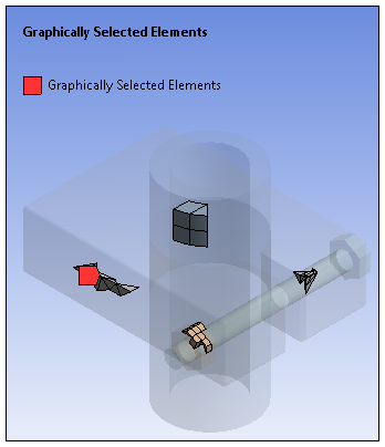
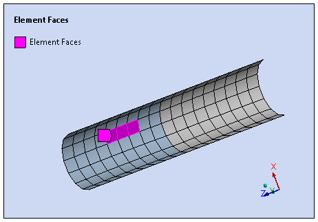
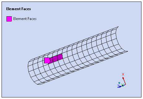
An example element-based Named Selection is illustrated below. The example is named Graphically Selected Elements. When the Show Mesh feature is active, as illustrated in the first image, the elements of a named selection (or multiple named selections) are highlighted. Otherwise, the elements are drawn and the remained of the model is transparent, as illustrated in the second image.
Show Mesh On Show Mesh Off 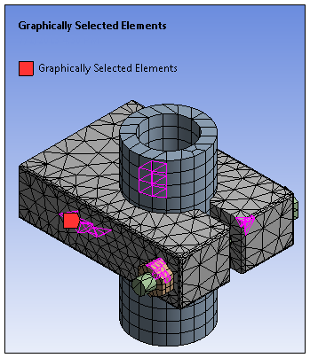
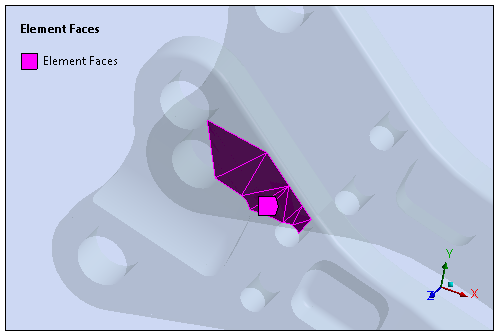
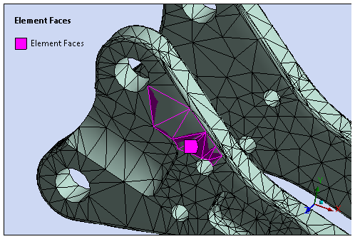
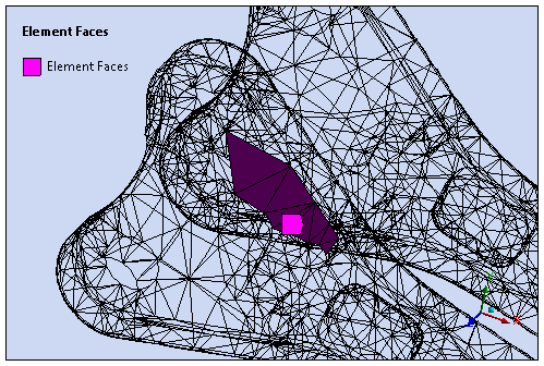
For Element Face-based Named Selections, each selected face is displayed and each face is “filled” as illustrated in the first image shown below. This is different from Element-based selections that only highlight/display edges. When the Show Mesh feature is active, the element faces of a Named Selections may present “bleeding” on the annotation as illustrated in the second image shown below. You can turn on Wireframe mode to accurately display annotations when Show Mesh is selected, as illustrated in the third image.
When working with Line Bodies and Surface Bodies: Ansys recommends that you turn off the option (Style group of the Display tab). This option changes the graphical display of the model’s thickness and as a result can affect how your element selections are displayed.
For surface body Element Face-based Named Selections, the selected element faces can become invisible as a result of being hidden behind an expanded mesh as illustrated below in the first two images below. This issue can again be remedied using Wireframe mode to accurately display annotations when Show Mesh is selected, as illustrated in the third image.
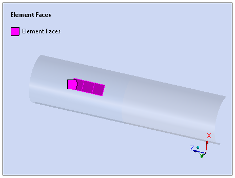
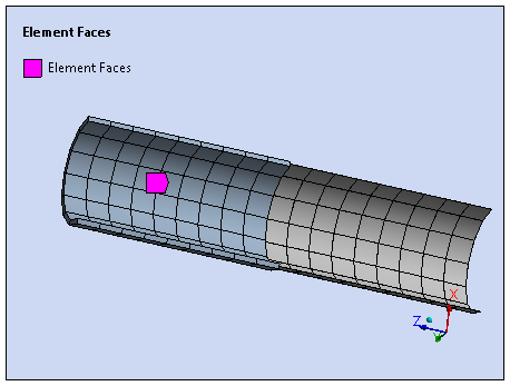
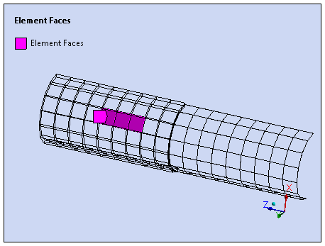
In addition, and as illustrated below in the first image below, not expanding the mesh (turn option off) displays the annotations properly. You can also use Wireframe mode, as illustrated in the second image below.
Viewing Element Information
As illustrated below, you can view information about your element/element face selections, such as Element Type, Element ID, as well as the body that the element is associated with using the Selection Information window. Once you have selected your desired element or elements, display the window by selecting the option from the Tools group on the Home tab.
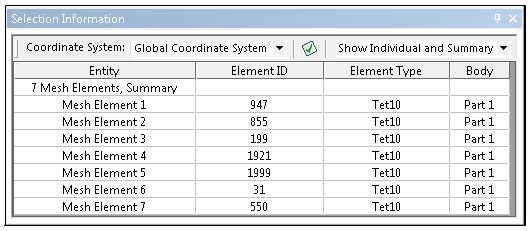
Note: The status bar at the bottom of the application window also displays the number of elements/element faces you currently have selected.
For additional information, see the Using the Selection Information Window section.


