


This section discusses cursor modes and how to select and pick geometry in the Geometry window. It includes information on the following:
| Pointer Modes |
| Highlighting |
| Picking |
| Blips |
| Painting |
| Depth Picking |
| Selection Filters |
| Selection Modes |
| Mini Selection Toolbar |
| Extend To |
For Help on how to select mesh nodes and elements, see the Selecting Nodes and Selecting Elements sections. Many of the same selection and picking tools are employed for mesh selections.
Pointer Modes
The pointer in the Geometry window is always either in a picking filter mode or a view control mode. When in a view control mode the selection set is locked. To resume the selection, repress a picking filter button.
The Graphics Toolbar offers several geometry filters and view controls as the default state, for example, face, edge, rotate, and zoom.
If a Geometry field in the Details Pane has focus, inappropriate picking filters are automatically disabled. For example, a pressure load can only be scoped to faces.
If the Direction field in the Details Pane has focus, the only enabled picking filter is Select Direction. Select Direction mode is enabled for use when the Direction field has focus; you never choose Select Direction manually. You may manipulate the view while selecting a direction. In this case the Select Direction button enables you to resume your selection.
Highlighting
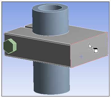
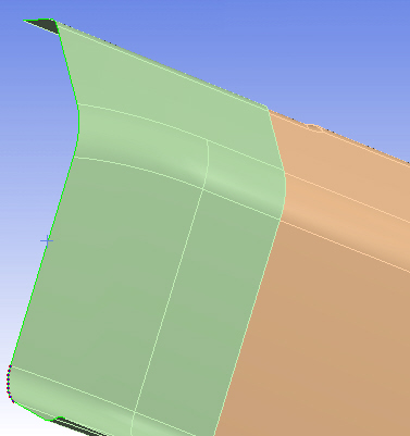
Hovering your cursor over a geometry entity highlights the selection and provides visual feedback about the current pointer behavior, for example select faces, and location of the pointer, for example, over a particular face.
As illustrated here, the face edges are highlighted in colored dots.
Picking
A pick means you select or "click" on a visible geometric entity. A pick becomes the current selection, replacing previous selections. A pick in empty space clears the current selection.
By holding the Ctrl key down, you can add additional selections or remove existing selections. Clicking in empty space with Ctrl depressed does not clear current selections.
For information on picking nodes, see Selecting Nodes.
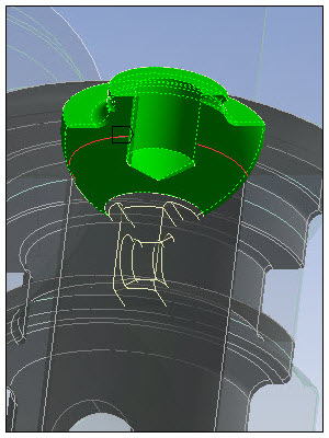
Blips
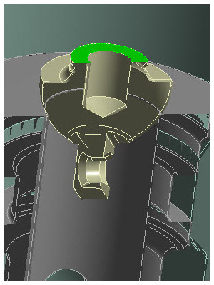
As illustrated below, when you make a selection on a model, a cross-hair “blip” appears.
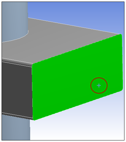
The blip serves to:
Mark a picked point on visible geometry.
Represent a ray normal to the screen passing through all hidden geometry.
When you make multiple selections using the Ctrl key, the blip is placed at the last selection entity. Clicking in empty space clears your current selection, but the blip remains in its last location. Once you have cleared a selection, hold the Ctrl key down and click in clear space again to remove the blip.
Note: This is important for depth picking, a feature discussed below.
Painting
Painting means dragging the mouse on visible geometry to select more than one entity. A pick is a trivial case of painting. Without holding the Ctrl key down, painting picks all appropriate geometry touched by the pointer.
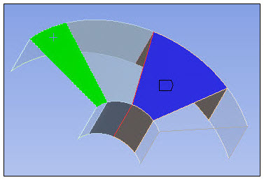
Depth Picking
Depth Picking enables you to pick geometry through the Z-order behind the blip.
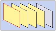
Whenever a blip appears above a selection, the Geometry window displays a stack of rectangles in the lower left corner. The rectangles are stacked in appearance, with the topmost rectangle representing the visible (selected) geometry and subsequent rectangles representing geometry hit by a ray normal to the screen passing through the blip, front to back. The stack of rectangles is an alternative graphical display for the selectable geometry. Each rectangle is drawn using the same edge and face colors as its associated geometry.
Highlighting and picking behaviors are identical and synchronized for geometry and its associated rectangle. Moving the pointer over a rectangle highlights both the rectangle its geometry, and vice versa. Ctrl key and painting behaviors are also identical for the stack. Holding the Ctrl key while clicking rectangles picks or unpicks associated geometry. Dragging the mouse (Painting) along the rectangles picks geometry front-to-back or back-to-front.
Selection Filters
When you are using your mouse pointer in the Geometry window, you are often selecting or viewing geometry entities or mesh selections. The Graphics Toolbar provides the geometry and mesh selection filters listed below. When you activate a filter, the specific entities (vertex, edge, face, body, node, or element) that you can select highlight as you pass your cursor over the entity. This helps you to make desired selections. You can use the filters with the options of the Select Mode drop-down list (that is, Single Select, Box Select, Box Volume Select, etc.).
Depressing the Ctrl key enables you to make multiple selections for a specific entity type. Furthermore, you can switch between modes (single, box, lasso, etc. as supported) and continue to add to your selection using the Ctrl key. You can release the Ctrl key while you change selection modes.
Smart Select
Vertex
Edge
Face
Body
Node
Element Face
Element
Selection Modes
The option enables you to select items designated by the Selection Filters through the Single Select or Box Select drop-down menu options.
Single Select (default): Click an item to select it.
Box Select: Define a box that selects filtered items. When defining the box, the direction that you drag the mouse from the starting point determines what items are selected, as shown in the following figures:
Dragging to the right to form the box selects entities that are completely enclosed by the box.
Visual cue: 4 tick marks completely inside the box.
Dragging to the left to form the box selects all entities that touch the box.
Visual cue: 4 tick marks that cross the sides of the box.
Box Volume Select: Available for node-based Named Selections only. Selects all the surface and internal node within the box boundary across the cross-section. The line of selection is normal to the screen.
Lasso Select: Available for node-based Named Selections only. Selects surface nodes that occur within the shape you define.
Lasso Volume Select: Available for node-based Named Selections only. Selects nodes that occur within the shape you define.
Note: Selection shortcuts:
You can use the Ctrl key for multiple selections in both modes.
You can change your selection mode from to by holding the right mouse button and then clicking the left mouse button.
Given a generated mesh and that the Mesh Select option is active, holding the right mouse button and then clicking the left mouse button scrolls through the available selection options (single section, box selection, box volume, lasso, lasso volume).
For Help on how to select mesh nodes and elements, see the Selecting Nodes and Selecting Elements sections. Many of the same selection and picking tools are employed for mesh selections.
Pointer Modes
The pointer in the Geometry window is always either in a picking filter mode or a view control mode. When in a view control mode the selection set is locked. To resume the selection, repress a picking filter button. The Graphics Toolbar offers several geometry filters and view controls as the default state, for example, face, edge, rotate, and zoom.
If a Geometry field in the Details Pane has focus, inappropriate picking filters are automatically disabled. For example, a pressure load can only be scoped to faces.
If the Direction field in the Details Pane has focus, the only enabled picking filter is Select Direction. Select Direction mode is enabled for use when the Direction field has focus; you never choose Select Direction manually. You may manipulate the view while selecting a direction. In this case the Select Direction button enables you to resume your selection.
Mini Selection Toolbar
When you are making geometric selections on your model, such as scoping contact conditions, boundary conditions, and/or results, a mini toolbar automatically displays in the Geometry window. This toolbar enables you to make selection changes "on the fly." Toolbar options include:
Apply Selection: Replace scoping with the current geometry selection.
Add to: Add the current geometry selection to the existing scoping.
Remove from: Remove the current geometry selection from the existing scoping.
In addition, when you are using the Smart Select option option, an option to select the parent body of your current selection is also available on the toolbar.
Extend To
The group, on Selection tab as well as the Extend drop-down menu on the Graphics Toolbar, is enabled only for edge or face selection modes and only with a selection of one or more edges or faces. The following options are available in the drop-down menu:
Note: For all options, you can modify the angle used to calculate the selection extensions in the WorkbenchOptions dialog setting Extend Selection Angle Limit under Graphics Interaction.
- Adjacent
For faces, the option searches for faces adjacent to faces in the current selection that meet an angular tolerance along their shared edge.
Single face selected in part on the left.
Additional adjacent faces selected after option is chosen.
For edges, the option searches for edges adjacent to edges in the current selection that meet an angular tolerance at their shared vertex.

Single edge selected in part on the left.
Additional adjacent edges selected after option is chosen.
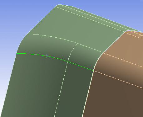
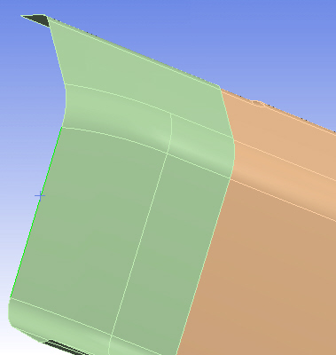
- Limits
For faces, the option searches for faces that are tangent to the current selection as well as all faces that are tangent to each of the additional selections within the part. The selections must meet an angular tolerance along their shared edges.
Single face selected in part on the left.
Additional tangent faces selected after option is chosen.
For edges, the option searches for edges that are tangent to the current selection as well as all edges that are tangent to each of the additional selections within the part. The selections must meet an angular tolerance along their shared vertices.
Single edge selected in part on the left.
Additional tangent edges selected after option is chosen.
- Instances
(Available only if CAD pattern instances are defined in the model): When a CAD feature is repeated in a pattern, it produces a family of related topologies (for example, vertices, edges, faces, bodies) each of which is named an "instance". Using , you can use one of the instances to select all others in the model.
As an example, consider three parts that are instances of the same feature in the CAD system. First select one of the parts.
Then, choose . The remaining two part instances are selected.
See CAD Instance Meshing for further information.
- Connection
As described in Define Connections, connections can be contact regions, joints, and so on.
searches for faces that are adjacent to the current selection as well as all faces that are adjacent to each of the additional selections within the part, up to and including all connections on the selected part. This does not include all faces that are part of a connection—it includes only those faces that are part of a connection and are also on the selected part.
If an edge used by a connection is encountered, the search stops at the edge; a face across the edge is not selected. If there are no connections, all adjacent faces are selected. If the current selection itself is part of a connection, it remains selected but the search stops.
Note:The extent of the faces that will be included depends greatly on the current set of connections, as defined by the specified connections criteria (for example, Connection Type, Tolerance Value, and so on). By modifying the criteria and regenerating the connections, a different set of faces may be included. Refer to Connection Features and Operations for more information.
The figures below illustrate simple usage of the option.
Single face selected in part.
Additional connected faces selected after option is chosen.

Single face selected in part. In this example, a multiple edge to single face connection is defined.
Additional connected faces selected after option is chosen. When the connection is encountered, search stops at edge.