


The Home tab displays by default when you open the application.

This tab contains the following Groups.
Outline
The Outline group provides options that enable you to make basic changes to Outline pane objects.

Options for this group include:
| Option | Description |
|---|---|
| and | Duplicates a selected Outline object. This option is only available if an object supports being duplicated. A drop-down menu is also available from this option. Once you have solved your analysis, the additional option becomes available in the drop-down. This option is only available when you select a result object. It duplicates your selected result object, including all subordinate objects. This is a faster option than duplicating a result that includes result data. |
| // | Cuts, copies, or pastes Outline objects. |
| Deletes a selected Outline object. | |
| Displays the dialog that enables you to search Outline objects, such as the name of an object or objects or a string of characters that are included in the name of objects. | |
Displays a drop-down menu of the following options:
|
Solve
The Solve group provides options that enable you to specify some basic solution configurations and to solve your analysis.

Options for this group include:
| Option | Description |
|---|---|
| / | Provides a drop-down menu to specify your desired selection only. |
| Distributed | Selected by default, this option enables and disables the ability for a distributed solution. |
| Cores | Specify the number of cores to use during the solution.
The default is value is 4. Entering 0
does not send any request to the Mechanical APDL solver related to the number of cores to
use. For shared-memory solutions, if you specify a number greater than the number of
cores in the node, the highest available number of cores is used. |
| Solve | Displays a drop-down menu for and solution selections. Initiates the solution when selected. |
| Resource Prediction | Opens a window that enables you to select an available analysis and then generate an estimate of the computing resources needed to perform a solution for the environment. |
| Solve Process Settings | 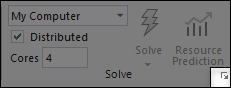 |
Note: The Solve drop-down menu and dialog options are also available on a number of Context tabs (Environment, Solution, etc.).
Insert
The Insert group provides a variety of regularly used options.

Options for this group include:
| Option | Description |
|---|---|
| Analysis | Displays a drop-down menu of standalone analysis selections to add to your existing model. A corresponding analysis system, with the appropriate connections, is also included in the Project Schematic. The new analysis shares the Engineering Data, Geometry, and Model cells with the other analysis systems under the model. |
| Named Selection | For a supported parent object, inserts a Named Selection, and parent folder as needed, into the Outline. |
| Coordinate System | This option is available when the Coordinate Systems object is selected. It inserts a new Coordinate System object. |
| Remote Point | This option is available when the Model object is selected. It inserts a new Remote Point object and parent folder as needed. |
| Commands | For a supported parent object, inserts and specifies a new Commands object. |
| Comment | For a supported parent object, inserts and specifies a new Comment object. |
| Chart | Inserts and specifies a new Chart object. |
| Images | Displays a drop-down menu of the following options:
|
| Section Plane | Displays the Section Planes window to specify a section cut-through on your model in order to view a cross section of your geometry, mesh, or of a result. See the Creating Section Planes section for additional information about this feature. |
| Annotation | Adds a text comment to a particular spot of your model. See the Graphics Annotations Window section for additional information about this feature. |
Tools
The Tools group provides a variety of display-based options.

Options for this group include:
| Option | Description |
|---|---|
| Units | Displays the Unit Systems drop-down menu. Modify unit system as desired. Note: The and settings are not available if you select either of the U.S. Customary settings. |
| For a supported objects, displays (or hides) the Worksheet window. | |
| Keyframe Animation | Displays the Keyframe Animation window. |
| Tags | Displays the Tags window to apply meaningful labels to objects that can then be filtered. See the Tagging Objects section for additional information about this feature. |
| Wizard | Activates the Mechanical Wizard. This feature helps you construct your simulation. |
| Show Errors | Displays error messages, in the Messages window, for
invalid Outline pane objects. Once you correct an invalid
object, selecting this option removes the error message from the window. Note: Even though the application does not check for solution and mesh related errors with this feature, selecting the option may also clear those errors from the Messages window. |
| Manage Views | Displays the Manage Views window. This feature enables you to save a graphical view of your model. |
| Selection Information | Displays the Selection Information window. |
| Unit Converter | Displays a Unit Conversion tool. It is a built-in conversion calculator that enables you to perform conversions between consistent unit systems. The Units menu sets the active unit system. The status bar shows the current unit system. The units listed in the tool and in the Details pane are in the proper form (include no parenthesis). |
| Print Preview | Displays a printable image of the currently selected object. See the Print Preview section for more information about this feature. |
| Report Preview | Displays your analysis in the Report Preview view. See the Report Preview section for more information about this feature. |
| Key Assignments | Displays a dialog that lists all available hotkey and hotkey combinations that enable you to quickly perform certain actions. See the Key Assignments section for more information. |
Layout
The Layout group provides options to manage the display of the interface.

Options for this group include:
| Option | Description |
|---|---|
| Full Screen | Activates a full screen display. This display can also be turned on and off using the F11 key. |
| Manage | Provides a drop-down menu of interface display selections. |
| User Defined | Displays a drop-down menu of the following options:
|
| Reset Layout | Restores the interface layout to the default setting. |