


A line body consists entirely of edges and does not have a surface area or volume. Although multiple CAD sources can provide line bodies to Ansys Workbench, only DesignModeler and Ansys SpaceClaim Direct Modeler provide the additional cross section data needed to use line bodies in an analysis. For those CAD sources that cannot provide the cross section data, you need to import them into DesignModeler or Ansys SpaceClaim Direct Modeler, define the cross sections, and then send the geometry to the Mechanical application in Ansys Workbench. Cross sectional data is imported into Mechanical and provided by Cross Section Objects.
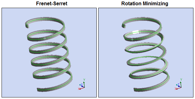
In addition to specifying the cross section type and offset, DesignModeler and SpaceClaim also allow you to align cross sections to ensure they have the proper orientation. For more information on Frame Alignment and how to override the default alignment algorithm, see Cross Section Alignment. Illustrated below are examples of the alignment algorithm options from DesignModeler.
Go to a section topic:
Note: See the Line Body Results section for additional information about the display of results scoped to line bodies.
Overview
Once imported, a line body is represented by a Line Body object in the tree, where the Details pane includes the associated cross section information of the line body that was defined in SpaceClaim Direct Modeler, DesignModeler, or supported CAD system. Depending on your application, you can further define the line body using the Model Type property. Options include , , , , (thermal analysis only), , or the read-only option . Review the following guidelines:
(BEAM188/BEAM189): This option is usually a suitable option when analyzing thin to moderately thick beam structures. A variety of cross-sections can be associated with beams.
Note: When a beam body is meshed with BEAM188, KEYOPT(3) = 2 (the quadratic shape function) is written to the input file. This differs from the usual default setting of BEAM188 in Mechanical APDL (KEYOPT(3) = 0, linear shape function). Note that this element is a lower order element and is only used when the Mesh object property Element Order is specified as , either by you as the user or by the application. See the Mechanical APDL Element Reference for BEAM188 for more information.
(PIPE288/PIPE289/ELBOW290): This option is suitable for analyzing initially circular cross-sections and thin to moderately thick pipe walls. You can apply special loads on pipes such as Pipe Pressure and Pipe Temperature. Curved pipe zones or high deformation zones in pipes can be further modeled using the Pipe Idealization object.
(LINK180): This option is a suitable option when analyzing uniaxial tension-compression scenarios. For stress and strain output, the Mechanical APDL solver only produces the AXL component (such as SX, EPELX, EPPLX, ...). This element type is not supported by the Beam Tool or the Beam Probe.
Note: Meshing does not distinguish between the different types of 1D elements in the meshing process. Hence, beam orientation nodes are created for beam elements and Link elements even though Link elements do not need any orientation nodes. The beam orientation nodes created for the Link elements are not getting connected to the Link elements but are simply ignored during the solution process.
(LINK180/CABLE280): This option enables you to simulate tensile load transfer along the length of the line body. For a linear order mesh, this option uses the LINK180 element. When the Element Order property of the Mesh object is set to or for a quadratic order mesh, this option uses the CABLE280 element. For stress and strain output, the Mechanical APDL solver only produces the AXL component (for example, SX, EPELX, EPPLX,...). The element types do not support the Beam Tool or the Beam Probe.
Note: Linear element order creates LINK180 elements with Tension and Compression setting as default TENSKEY for SECCONTROL.
: Thermal fluid flow models heat distribution between fluid and solid bodies during steady-state and transient thermal analyses. This selection activates the Mechanical APDL element FLUID116 with TEMP (Temperature) as the degree of freedom. Activating Fluid Flow (via Convection) is equivalent to a reduced-order model for a Computational Fluid Dynamic (CFD) analysis, for a one-dimensional fluid flow. This provides an accurate solution that does not require significant computation time. Heat flow is generated by the conduction within the fluid and the mass transport of the fluid.
Limitation: If your analysis includes the material property Specific Heat, defined in Engineering Data, the Thermal Fluid setting only supports Specific Heat defined at Constant Pressure.
Reinforcement (REINF264): This option models a line body as a reinforcement within a structure. It is supported for 3D Static Structural and Steady-State Thermal analyses only and requires that your imported model already include the line bodies you wish to specify as reinforcements as well as an appropriate material to assign to the reinforcement bodies.
(SHELL208/SHELL209): This read-only option is only displayed when you create a Line Body from a Line Coating using the Pull feature.
Note: For the and options, the application meshes the line body with only one element if the body is a line with a single edge. You can override this behavior by specifying a mesh Sizing control that has the Behavior property set to .
Application
To define your line body, highlight the Line Body object and set the following in the Details view:
Stiffness Behavior: As applicable, use this property to modify the stiffness behavior of the line body. Options include (default) and .
Coordinate System: As needed, use this property to change the assigned default coordinate system.
Reference Temperature: As needed, use this property to change the default reference temperature that is taken from the environment.
Cross Section: Select a cross section from the drop-down list of available Cross Section Objects. This property is not visible when the Model Type property (below) is set to .
Offset Mode: Set to Refresh on Update (default) to enable the values in the Details view to update when the CAD system updates or to Manual, to enable the Details view values to override the CAD system updates.
Offset Type: Set to Centroid, Shear Center, Origin, or User Defined, where Offset X and Offset Y are available.
Model Type: Options include Beam (default), (thermal analysis only), , , , or . Note the following specifics for certain options.
- Thermal Fluid
When you select the option, you need to evaluate the following additional properties:
Fluid Cross Area: Defines the fluid cross-section area of the Line Body. You can modify this value, however; by default, the application uses the value provided by your geometry application. And, updating your source Geometry resets this property to the default value.
Discretization: Options include , , and . Refer to the Discretization scheme described in the Mechanical APDL Element Reference for FLUID116.
- Link/Truss
When you select the option, the Behavior property also displays. Options include (default), , and .
- Reinforcement
This option enables you to specify line bodies as reinforcing fibers inside of a structure.
- Axisymmetric Shell (Read-Only)
Only visible for a Line Body created from a Surface Coating. This is available using the mesh-based Pull feature. Review display characteristics in the Line Body Results section.
Cross Section (For Solver): This property displays when your Line Body includes a user-defined cross-section. It enables you to send user-defined cross-sections to the MAPDL solver as either a (default) cross-section or as a section. These options are specified in the Geometry preference category of the Options dialog.
Selecting sends the integrated cross-section inertia properties, calculated in DesignModeler or Ansys SpaceClaim Direct Modeler, to the solver using the SECTYPE,,BEAM,ASEC command. The option sends the mesh section data, generated in DesignModeler or Ansys SpaceClaim Direct Modeler, to the solver using the SECTYPE,,BEAM,MESH command. The option enables you to post process results on the entire mesh section.
Note: You may see slight result differences between the Pre-integrated and Mesh settings as a result of how the application performs the calculations. There are certain limitations associated with the cross-section input data when using the Pre-integrated setting.
Specify Material category properties as needed.
See the Body object reference section for a complete listing of all Line Body properties.
Thickness Display
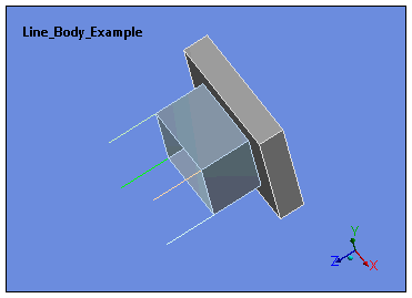
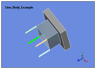
As illustrated below, you can increase the thickness of a line body's graphical display in the Geometry window by changing the default setting of the Line Body Thickness property in the Graphics preference of the application Options.
|
|
|
Beams can also be used as connections within a model. See Beam Connections for further information on this application.
Pipes are only realized in structural analyses. All line bodies defined in other analysis types are always realized as beams. This extends to linked analyses as well. For example, in a thermal-structural linked analysis where line bodies are defined as pipes, the thermal component of the analysis will only realize the line bodies as beams.
Cross Sections
By default, line bodies are displayed as lines in the Geometry window, with no graphical indication of a cross section. If cross sections are defined in a line body, you can select the option from the Style group of the Display tab to display the line bodies as solids (3D), enabling you to visually inspect the cross sections. This visualization can be useful in determining the correct orientation of line bodies. For circular and circular tube cross sections, the number of divisions used for rendering the line bodies as solids has an adjustable range from 6 to 360 with a default of 16. You can adjust this using the Number of Circular Cross Section Divisions option in the Graphics category of the dialog.
The display option has the following characteristics:
By default, the feature is not enabled. However, when activated, it will persist as a session preference.
Only geometry displays are applicable. The feature is not available for mesh displays.
When the feature is enabled, both normal lines and solid representations are drawn.
The solid representation of the geometry cannot be selected nor meshed, and has no effect on quantitative results.
The feature supports section planes and works with all line body cross sections (primitive and user defined).
User Integrated cross sections (direct entry of the properties) have no display.
The feature is not available for use with viewports.
This feature is not supported on the Linux platform.
When you import geometry from an External Model system, geometric edges may be collapsed and not display the actual orientations that are specified in the external model file.
Tip: Use the Show Mesh option to visualize the proper orientations as defined in the file. These are the orientations that the application sends to the solver.