


The Section Plane feature creates cuts or slices on your model so that you can view internal geometry, mesh, and/or result displays. The graphical display and operation of the feature varies depending upon whether you are displaying your model as geometry or if you are displaying the mesh or a result. You can create as many as six active Section Planes for a model. Once this maximum is met, you can add additional planes, but you cannot activate (or view) them until you have deactivated (unchecked) an existing plane and then activated the desired plane.
Tip: Activate the Consider Section Planes When Mesh Picking preference in order to select newly displayed finite element entities (nodes, elements, and element faces) from geometries within the model that were hidden before adding the specified Section Plane. Review the Selecting Mesh Entities Displayed by the Section Plane topic at the end of the section to make sure that you understand the requirements and limitations of this feature.
Go to a section topic:
See the next two sections, Understanding Section Plane Display Differences and Working with Section Plane Results, for information about display differences for section planes as well as display characteristics for when you apply a Section Plane to a result.
Application
Select the Section Plane option from the Insert group of the Home tab to open the Section Planes window illustrated below. The window displays a list of existing section planes (once created) and also provides the tools used to add, modify, or delete you section planes.
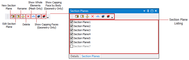
Note: The Section Planes tool supports up to six (6) defined planes. Once you exceed six, unchecking an existing plane enables you to activate any defined planes greater than six.
Section Plane Tools
The Section Planes window provides the following tools. You toggle these tools on and off by selecting the button.
- New Section Plane
Select this option and create a new Section Plane in the Geometry window. Drag the mouse pointer across the geometry where you want to create a section plane. The new section plane automatically displays in the Section Planes window with a default name of "Section Plane #." The checkmark next to the plane's name indicates it is an active section plane. You can construct additional Section Planes by clicking the New Section Plane button and dragging additional lines across the model. Note that activating multiple planes displays multiple sections.
Important: Note that for incidences, such as very large models, where the accessible memory is exhausted, the New Section Plane tool reverts to a Hardware Slice Mode that prohibits the visualization of the mesh on the cut-plane.
- Edit Section Plane
Highlight one of the Section Planes available in the window listing and then select this option to edit the highlighted section plane.
To edit a section plane:
In the Section Planes window, select the plane you want to edit.
Click the Edit Section Plane button. The section plane's anchor appears.
Drag the Section Plane or Capping Plane anchor to change the position of the plane.
You can click the line on either side of the anchor to view the exterior on that side of the plane. The anchor displays a solid line on the side where the exterior is being displayed. Clicking the same side a second time toggles between solid line and dotted line, that is, exterior display back to section display.
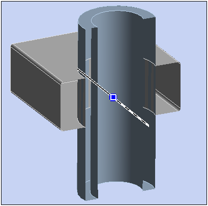
This animation shows the result of dragging the anchor (not visible for PDF versions of the Help).
- Delete Section Plane
This option deletes a selected Section Plane from the listing.
- Rename Section Plane
Select this option to rename a Section Plane.
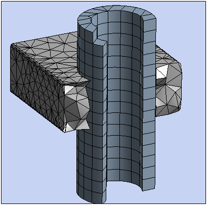
- Show Elements
When you have the Mesh object selected or you have the Show Mesh feature activated, this selection causes any partially sliced elements to display entirely.
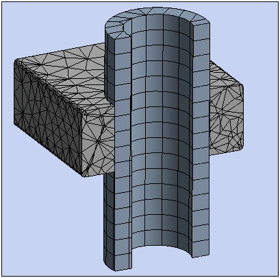
When you are viewing a Mesh display, you can use the Show Whole Elements button to display the adjacent elements to the section plane which may be desirable in some cases.
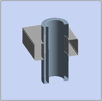
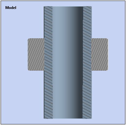
- Show Capping Faces
When only one Section Plane is contained in the window, by default, the slice is not capped and you can see the interior of the geometry. Selecting this option caps the geometry.
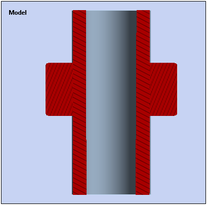
- Show Capping Faces by Body Color
This selection works in tandem with the Show Capping Faces option. Selecting this option changes the color of the capped geometry surface to match the body color of the geometry.
Note: Certain objects that display geometry annotations may not correctly display capping. Examples include contact objects, joints, and objects displaying spatially varying loads.
Caution: When using the Section Planes feature with shell bodies, make sure that the view option is turned on. Turning this view feature off changes the graphical display. The coloring for the top and bottom surfaces can degrade. So much so that the application could display both sides of a section plane simultaneously and as a result, the application could display inaccurate results.
Selecting Mesh Entities Displayed by the Section Plane
`
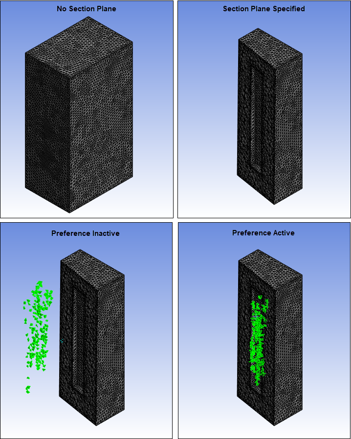
When you activate the Consider Section Planes When Mesh Picking preference, the application displays finite element entities (nodes, elements, and element faces) from geometries within the model that were not visible before adding the specified Section Plane. As illustrated below, in previous versions of the application, the application unexpectedly picked finite element entities on the hidden geometries (of the Section Plane). The application essentially did not recognize a Section Plane existed. This preference addresses the graphical selection limitation.
Note: This preference:
Is supported for all active section planes.
Does not support capped faces.
Supports all selection modes: single, box, lasso and volume.
Supports direct mesh selection on results.