


As with geometry selection, you use many of the same selection tools for mesh nodes. Once you have generated the mesh on your model, you use picking tools to select individual or multiple nodes on the mesh. You use node selections to define objects such as a node-based coordinate system or node-based Named Selections as well as examining solution information about your node selections. This section describes the steps to create node-based objects in Mechanical.
The following additional topics included in this section describe the uses for the node selection feature:
Also see these sections for the steps to create node-based coordinate systems and Named Selections.
Node Selection
To select individual nodes:
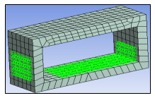
Generate a mesh by highlighting the Mesh object and clicking the Generate Mesh button.
From the Graphics Toolbar, select the filter option.
As needed, choose the appropriate selection tool from the drop-down list. For more information on the node-based selection modes, see Selection Modes for Node Selection.
Note:When working with Line Bodies: Nodes can be selected using volume selection modes only ( or ).
When working with Line Bodies and Surface Bodies: Ansys recommends that you turn off the option ( tab). This option changes the graphical display of the model’s thickness and as a result can affect how your node selections are displayed.
Select individual nodes or define the shape to select nodes. With your selections active, you can now define a coordinate system or named selection from selected nodes.
Selection Modes for Node Selection
|
| Selects individual nodes or a group of nodes on the surface. | ||
|
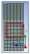
| Selects all the surface nodes within the box boundary for all the surfaces
oriented toward the screen.
| ||
|
| Selects all the surface and internal nodes within the box boundary across the
cross-section. The line of selection is normal to the screen.
| ||
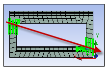
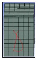
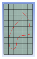
|
| Is similar to the Box Select mode. Selects surface nodes
that occur within the shape you define for surfaces oriented toward the screen.
| ||
|
| Similar to Box Volume Select mode. Selects the nodes that
occur within the shape you define.
|


Tip:
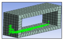
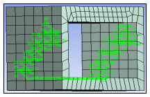
To select multiple nodes, press the Ctrl key or press the left mouse and then drag over the surface. You can also create multiple node groups at different locations using the Ctrl key.
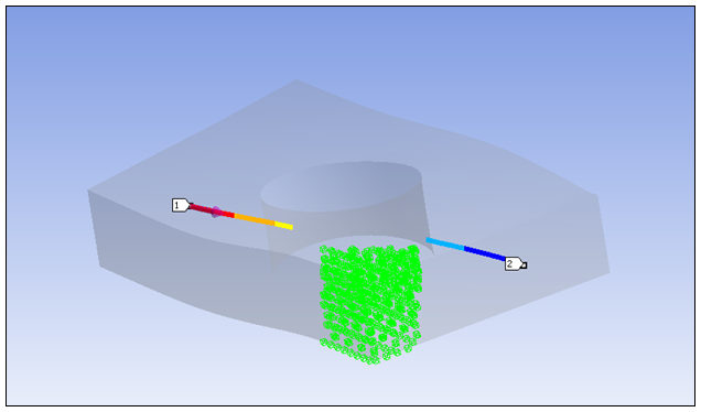
To select all internal and surface nodes, use the Box Volume Select or Lasso Select tool and cover the entire geometry within the selection tool boundary.
The (Ctrl+A) option is not available when selecting nodes.
View Node Information
You can view information such as the location of each selected node and a summary of the group of nodes in the Selection Information window. A brief description of the selected nodes is also available on the status bar of the application window. To view node id and location information:
Select the nodes you wish to examine.
Select the option from the Tools group on the Home tab.
The following options are available as drop-down menu items in the window.
| Selection Information | Description |
|---|---|
| Coordinate System | Updates the X, Y, and Z information based on the selected coordinate system. |
| Show Individual and Summary | Shows both the node Summary and information on each node. |
| Show Individual | Shows information related to each node. |
| Show Summary | Shows only a summary of selected nodes. |
For more information see the Using the Selection Information Window section.
Select Mesh Nodes on a Result Contour
Nodes (from the original mesh) can be selected even if they don’t have values for the selected result, as in a path or surface scoped result.
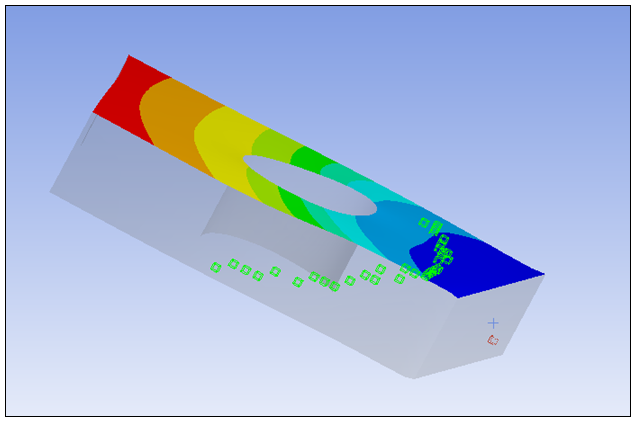
The positions of selected nodes reported in the Selection Information window are those from non-deformed mesh.
Note: If the graphics expansion is used (for shells and cyclic expansion, for example), the selection will work on the expanded graphics, while the reported node ID and position will be those in the non-expanded mesh. To eliminate confusion, switch the expansion off.