This section is intended to provide you with tips and strategies for avoiding and handling problems that may occur when using the Meshing application. Topics include:
Meshing Process
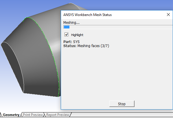
When you generate mesh, the mesh is generated as a separate process per part. If there are multiple parts, each part can be meshed in parallel. While meshing, the status of meshing is displayed in the bottom left-hand side of the screen where an interrupt button is also available. When you double-click on the mesh status, Ansys WorkBench Mesh Status window displays the detailed information on the meshing progress on parallel cores.
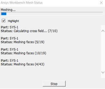
Other information, such as the amount of memory used can be found by using a task manager.
While the mesher is working at certain points it will highlight topology (edges, faces, bodies). If the mesher gets stuck for a long time on a particular topology, you should inspect the highlighted topology and possibly merge it with another topology using virtual topology, adjust the mesh sizes in that area or return to a geometry tool to investigate and fix the problematic location.
For details about topology highlighting during the meshing process, refer to Generating Mesh. For information about how to set the default for topology highlighting, refer to Meshing Options on the Options Dialog Box.
Identifying Poor Quality Mesh
The following approaches are recommended to improve the mesh quality and obtain a valid mesh:
Set the Display Style to identify quality by color.
Use the Mesh Metric option to view information about a number of quality statistics and set Min/Max values to find poor quality elements.
Use the Worksheet as your Scoping Method and use worksheet data to define criterion-based measurements.
Recommended First Course of Action for Meshing Failures
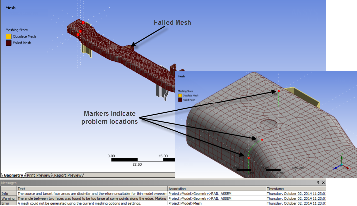
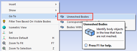
If your mesh generation fails, it may be a partial or complete meshing failure. Your first course of action should be to examine any messages that the mesher returns to the Messages window. The messages include hints that explain why the meshing completely or partially failed. In some cases, you can right-click the message and select Show Problematic Geometry to highlight any entities associated with the message in the Geometry window and see what the failed mesh looks like. If the geometry contains many bodies and only a few have failed to mesh, to isolate the bodies that failed to mesh, right-click the Geometry window and click Go To > Unmeshed Bodies. Other bodies can then be hidden.
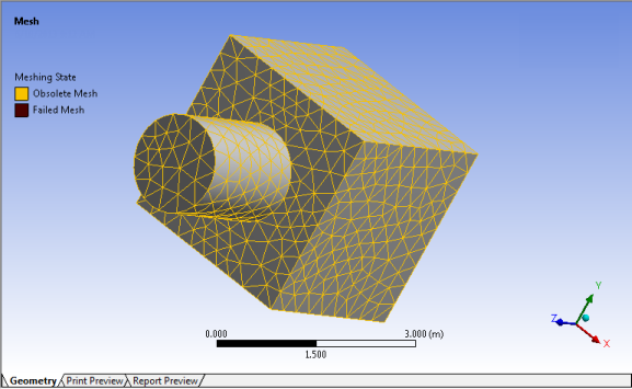
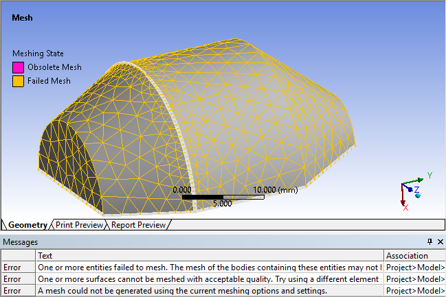
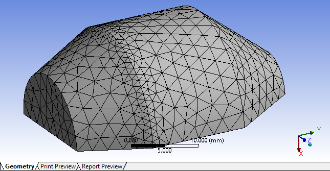
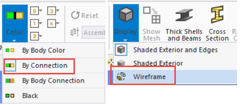
The mesher helps you to visually identify obsolete or failed meshes. As shown in the figures below, failed meshes are shaded in maroon and obsolete meshes are colored yellow. The approximate location the meshing failure is identified by a convergence of white lines. If this is not clear, color by connectivity can be enabled to identify the point at which unmeshed face edges will be marked as red (single connectivity) and if you switch to wireframe mode these locations can be seen more clearly.
If the entities are very small, you can refer to the status bar at the bottom of the window to view statistics related to the entities. Then create a Named Selection to retain information about the problematic entities. Continue reading below for more information about messaging.
Understanding Messaging
The Messages window prompts you with feedback concerning meshing operations. Every message returned from the mesher is not necessarily an error. Messages come in three forms:
Error: Requires action from you to obtain a mesh.
Warning: Guides you in best practices or alternative courses of action. A warning does not require you to fix any problems, but may give an indication of a subsequent related error.
Information: Helps you make better decisions related to meshing your model or provides you with information about the approach the mesher used to mesh your model.
Once messages are displayed, you can:
Double-click a message to display its contents in a pop-up dialog box.
Highlight a message and then press the key combination Ctrl+C to copy its contents to the clipboard.
Press the Delete key to remove a selected message from the window.
Select one or more messages and then use the right mouse button click to display the following context menu options:
- Selects the object in the Tree Outline that is responsible for the message.
- Highlights the geometry in the Geometry window that is responsible for the message. This option is not always available.
- Creates two named selection groups. One named selection group has the failed body, and the other group contains the intersecting elements displayed by the Show Intersecting Surface Mesh.
- Displays the selected message in a pop-up dialog box.
- Copies the selected messages to the clipboard.
- Removes the selected messages.
- Refreshes the contents of the Messages window as you edit objects in the Tree Outline.
Understanding States
Sometimes the mesher returns an invalid mesh. Refer to the state of the body in the Tree Outline to determine whether a body was meshed:
A check mark
 denotes a body in a
fully defined but unmeshed state.
denotes a body in a
fully defined but unmeshed state.A check mark with a hash
 denotes
a meshed body.
denotes
a meshed body.A question mark
 denotes a body
that needs more information before it can be sent to the solver.
When your model contains an active unmeshed body, the Mesh object in the Tree Outline is preceded by a lightning bolt to indicate a body is out-of-date and requires action:

When your model is in the process of being meshed, the Mesh object is preceded by a green lightening bolt to indicate that the meshing is in progress:

When your model is fully meshed (all bodies are in a meshed state), the Mesh object is preceded by a check mark to indicate that the meshing data is fully defined and ready for the next stage of your analysis (that is, an update in the Meshing application or a solve in the Mechanical application):

Understanding Mesh Connection and Contact Match States
Mesh connections and contact matches use the following symbols to denote mesh state:
A check mark
 denotes a
connection or match that is fully defined and ready to be connected or
matched.
denotes a
connection or match that is fully defined and ready to be connected or
matched.A check mark with a hash
 denotes a successful connection or
match.
denotes a successful connection or
match.A question mark
 denotes a
connection or match that is invalid that needs more information before it can be
connected or matched.
denotes a
connection or match that is invalid that needs more information before it can be
connected or matched.A circle with a bar in it
 denotes a connection or match that is ignored. Check the Details view of the mesh
connection or contact match for the reason.
 A lightning bolt
 indicates that the connection or match is out-of-date and requires action.
An ‘X’
 denotes a suppressed connection or match. Unsuppressing the connection or match
requires it to be reconnected or rematched even if it was previously connected or
matched.
Shape Checks and Meshing Failures
Meshing may fail if the mesh quality does not meet the criterion of the defined shape checks. The following approaches are recommended to improve the mesh quality and obtain a valid mesh:
To identify faces that do not meet the shape checking criteria, right-click the warning message and select .
Use a different shape check setting.
Some shape checks have a stricter set of criterion than others. By using a different shape check setting a mesh might be generated, and the mesh metrics bar graph can be used to find the mesh violating the stricter shape checks. In this way, locating the problem is the first step to fixing it.
Use the methods described in Identifying Poor Quality Mesh to determine the quality of the mesh.
Use the Preview Surface Mesh and/or Preview Inflation features.
With this approach the boundary mesh is generated even if the mesh would violate the defined shape checks. Once the previewed mesh is generated, use the mesh metrics bar graph to determine the location of bad quality elements. Generally, fixing the bad quality surface mesh is the best way to fix the volume mesh because bad quality mesh is usually a result of the geometry over-constraining the mesh topology. Using defeaturing controls (such as Loop Removal and Mesh Defeaturing), pinch controls, and virtual topologies are all good strategies to remove geometry features that may cause problems for the meshing algorithms.
For additional information about the shape checking acceptance criterion used by Ansys Workbench, refer to Ansys Workbench and Mechanical APDL Application Meshing Differences.
Handling Selective Meshing Failures
Selective meshing may lead to unexpected results in cases where a mesh control change affects only one body. This may in turn lead to sweep mesh failure because the source and target meshes no longer align or the resultant change makes a body unsweepable. If desired, you can set the Allow Selective Meshing option to No to disable selective meshing and allow the mesh control changes to ripple through the entire part.
Selective meshing is not persistent for a geometry update or re-mesh operation. However, you can use the Mesh worksheet to create a selective meshing history so that your meshing steps can be repeated in the desired sequence. Otherwise, you may need to go through your body meshing steps manually if the single mesh update does not satisfy your meshing requirements. Refer to Using the Mesh Worksheet to Create a Selective Meshing History for details.
Handling Failures due to Protected Topology
Improper set up of hard protected topology may result in meshing failures if the mesher cannot return a reasonable mesh while also respecting the topology.
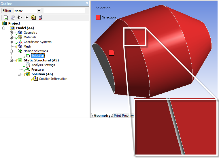
In the example, a sliver face is missing from the Named Selection defined. The Protected option is set to Yes.
The missing face could lead to problems during meshing since boundaries of hard protected topologies receive special treatment to ensure the mesh is properly associated. The special protection ensures the outer boundary is captured accurately, however, it could have a negative impact on meshing since the mesher is forced to capture the sliver surface. With the Highlight option enabled, the problematic face is highlighted during the meshing process (Figure 238: Problematic Topology Highlighted During Meshing). If a face is highlighted for a long period of time it can indicate a problem meshing the face. In this case, the problem comes from the protected topology.
The missing face could also lead to other meshing failures. For example, the sizing applied may be such that the mesher cannot return a reasonable mesh while also respecting the topology. In this case, the mesher may fail in face meshing while trying to protect the boundaries of the Named Selection. The faces that fail to mesh are indicated in the message window (use the right mouse button to select the error message to show the problematic geometry).
Examine the model to locate objects scoped to either the sliver face or the neighboring faces of the sliver face (Named Selection). By including the sliver face in the Named Selection definition, the mesh can be generated while respecting the sizing and the topology.
Handling Patch Independent Tet Meshing Failures
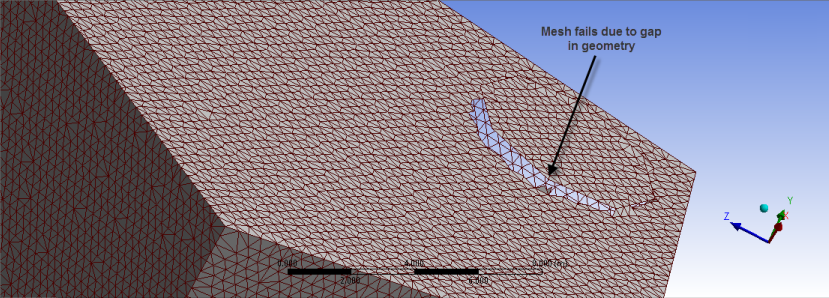
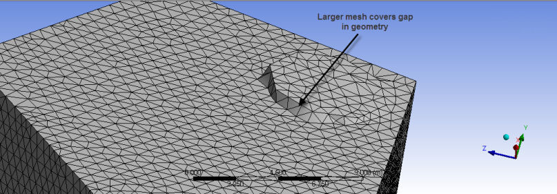
If there are gaps in your geometry and Patch Independent tet meshing fails, the mesh size may be set smaller than the size of the gaps in the geometry. In such cases, try adjusting the size of the mesh in those regions so they are larger than the geometry gap size.
Handling Patch Conforming Tetrahedral, Hex Dominant, Quad Dominant, and All Triangle Meshing Failures
Some mesh failures are due to an inappropriate defeature size (either default or user input) or dirty geometry. Use the following guidelines to determine which issue is the cause of the failure:
If a message provides "Problematic Geometry" information, use it to determine which portions of the model fail. Often, one or more faces fail to mesh.
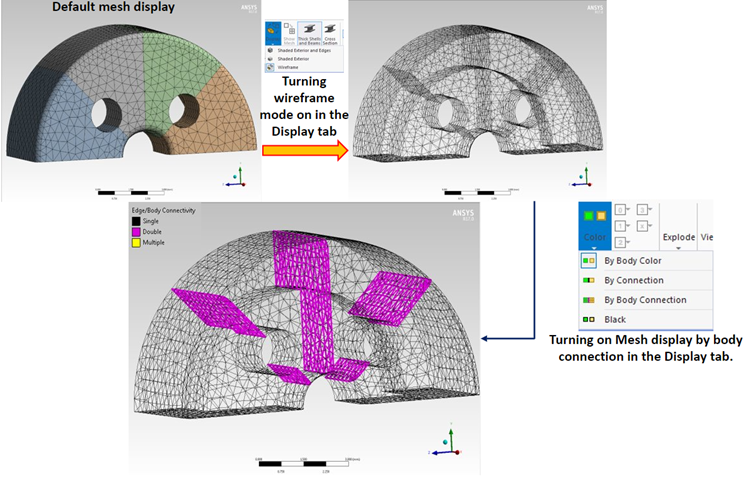
Use Diagnostic and Visualization Tools to help you find the problematic locations. Diagnostics for intersecting faces can point out issues where corrupted surface mesh is causing failure and can be linked to geometry corruption or defeaturing tolerances causing edge meshing issues. Switching on Edge Coloring > By Connection along with Wireframe display can highlight unmeshed faces very clearly with red edges. Diagnostics for Free Mesh Edges will also highlight these areas with Named Selections.
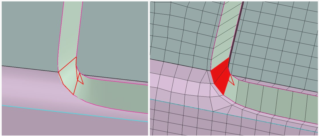
If a face fails to mesh, check whether the geometry looks problematic. Problems may arise if very sharp or thin faces exist or if faces are corrupted (the graphics may look strange/wrapped). If so, some options used to address the problem are as follows:
Add local size controls to reduce mesh size.
Add local size controls to modify defeaturing tolerance.
Merge faces locally using Virtual Topology.
Add a local Pinch control.
Modify the geometry in the problematic location using a geometry tool.
If a face fails to mesh but does not appear problematic at first inspection, check to see if the edges attached to that face may be problematic. For example:
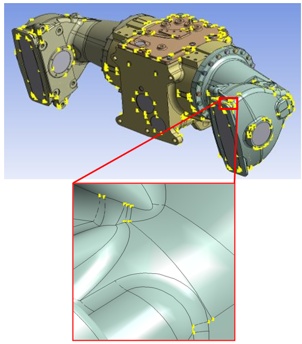
Turn on the Show Vertices and Close Vertices options to see if any edge is significantly faceted (that is, it has many edge splits in comparison to mesh size), or if there are any unexpected clusters of vertices. The mesher will try to respect geometric vertices, so unnecessary vertices can lead to complications in meshing that may be avoidable. Use of virtual topologies, pinch controls and so on, to handle in these situations.
For a multibody part, turn on the Edge Coloring > By Body Connection option to see if the edge connectivity is unusual between bodies.
Handling General Sweep Meshing Failures
In the event of a sweep mesh failure, the following approaches are recommended:
Check for contradicting edge sizings.
For Src/Trg Selection, use a manual setting instead of automatic.
Check side faces to see if they are mappable. Use of virtual topologies can help make bodies sweepable:
Turn on the Show Vertices and Close Vertices options to see if any edges have unnecessary splits. Extra edge splits can make faces that appear to be mappable more difficult to map. Virtual edges can help in these cases.
Use of virtual face splits can help make faces more mappable, as can use of the mapped face mesh control and its advanced options.
Turn on the Edge Coloring > By Connection option to see if the edge connectivity is unusual. In some cases, the geometry connectivity may not be as expected, and this may create problems during meshing. These problems could be fixed in the DesignModeler application, the CAD package, or possibly through the use of virtual topologies.
For a multibody part, turn on the Edge Coloring > By Body Connection option to see if the edge connectivity is unusual between bodies.
For detailed information about the requirements and characteristics of sweep meshing, refer to Mesh Sweeping.
For additional information, refer to Figure 7.36: Strategies for Avoiding Stretched Elements in the Mechanical APDL help.
Handling Thin Sweep Meshing Failures
In the event of a thin sweep mesh failure, first refer to Thin Model Sweeping for detailed information about the requirements and characteristics of thin sweep meshing.
The and features do not support the thin model sweeper. Thus, if a failure occurs, you must use the feedback in the Messages window to determine the problem:
If Src/Trg Selection is set to Automatic Thin, determine whether the correct source/target faces are being used. You can review the source/target faces by right-clicking the appropriate message. If incorrect source/target faces are being used, select the Manual Thin option on the sweep method and pick the correct faces manually.
In many cases, the messages tell you to use virtual topology to merge an edge/face. Thin sweeping requires one division through the thickness for multibody parts. Side edges must connect directly from source to target to comply with this rule.
If a message tells you the target faces are not meshed, try swapping the source/target faces.
In cases where a thin sweep body and a general sweep body are neighbors, the general sweep body has higher priority and is meshed first. The general sweep operation may place nodes on the side area/edge of the thin sweep body. If you receive a message describing this situation, you must apply additional mesh controls to prevent it.
If both source and target areas are meshed, thin sweep will fail. In this case, you must find some way to eliminate the situation.
Thin sweep may issue warning messages stating that the source you picked was swapped with the target, and that some controls on the target faces were ignored as a result. These types of warning messages are for your reference only.
Handling General MultiZone Meshing Failures
In the event of a MultiZone mesh failure, the following approaches are recommended:
If using automatic source face selection, try using manual source face selection (or vice versa). For manual source face selection, ensure that all sources and targets are selected. Refer to Using MultiZone for more information.
Ensure that all side faces are mappable. Refer to MultiZone Face Mappability Guidelines for more information. Use of virtual topologies can help make bodies sweepable:
Turn on the Show Vertices and Close Vertices options to see if any edges have unnecessary splits. Extra edge splits can make faces that appear to be mappable more difficult to map. Virtual edges can help in these cases.
Use of virtual face splits can help make faces more mappable, as can use of the mapped face mesh control.
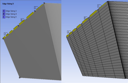
If MultiZone doesn’t respect edge biasing, as shown in Figure 243: Edge Biasing Not Respected by MultiZone below, it may be because the opposite edge is split. To work around this, perform the edge biasing on the opposite edges to get a better edge distribution, as shown in Figure 244: Edge Biasing Respected by MultiZone.
Note: When a curve with bigeometric distribution is split, the curve is split into GEO1 and GEO2 starting at the split point.
Turn on the Edge Coloring > By Connection option to see if the edge connectivity is unusual. In some cases, the geometry connectivity may not be as expected, and this may create problems during meshing. These problems could be fixed in the DesignModeler application, the CAD package, or possibly through the use of virtual topologies.
For a multibody part, turn on the Edge Coloring > By Body Connection option to see if the edge connectivity is unusual between bodies.
For detailed information about the requirements and characteristics of MultiZone, refer to MultiZone Meshing.
When the mesh fails without providing any useful message, you should try following:
Set sweep thickness slightly higher than the maximum thickness of the body.
Select source or target faces (try to select source and target faces completely, partial selection may return partial mesh).
When the mesh fails while performing Cart Sweep, you should try the following:
Select the source face.
Adjust cartesian size, you need to be careful about the sizes while performing Cart Sweep. For some cases, it works only with particular size.
Do not apply too many size parameters, it makes Cart Sweep overconstrained and mesh fails.
Ensure that there are no drafts in the model, Cart Sweep cannot handle drafts.
Handling Failed Mesh Connections
In the event of a mesh connection failure, refer to Diagnosing Failed Mesh Connections.
Handling Failed Contact Matches
In the event of a contact match failure, refer to Troubleshooting Failed Contact Matches.
Using Named Selection Diagnostics to Find Meshing Issues
The Diagnostics Action allows you to create Named Selections for the selected bodies which will highlight some key issues with the mesh that may need your attention to make it analysis-ready. Before adding a Diagnostics row to the worksheet, rows should be added to select relevant bodies to be used in the diagnostic checks as shown in the example below where all solid bodies are selected in the first row.

Several Criteria exist in the Diagnostics Action and depending on the Entity Type used, their effects areas follows:
| Entity Type | Criterion | Usage |
| Face | Defeatured | Shows where geometry Faces have been fully defeatured during meshing. |
| Edge | Defeatured | Shows where geometry Edges have been fully defeatured during meshing. |
| Edge | Partially Defeatured | Shows where geometry Edges have been partially defeatured during meshing. |
| Vertex | Defeatured | Shows where geometry Vertices have been fully defeatured during meshing. |
| Mesh Node | Free Mesh Edges | Shows mesh nodes at edges which are open. That is, if volume meshing has failed due to unmeshed faces it will highlight these areas. |
| Mesh Element | Intersecting Elements | Shows where mesh elements are intersecting causing meshing failure.
Useful for troubleshooting failed-to-mesh bodies. The fixes can be as follows:
|
| Mesh Element | Body Interference Elements | Shows mesh elements which are intersecting due to bodies overlapping in 3D space. Elements at the surface intersection are selected. Geometry tools may be needed to repair such areas if overlaps are deemed too large. |
| Mesh Element | Sharp Angle Elements | Shows mesh elements which are flat due to geometry faces coming together at a tangent or sharp angle. Useful to diagnose geometry problems causing bad quality elements. Such problems may need to be fixed in a geometry editor by addition of a chamfer or round. For example, using Pull in Discovery or SpaceClaim. |
| Mesh Element | Free Mesh Edges | Shows mesh nodes at edges which are open. That is, if volume meshing has failed due to unmeshed faces it will highlight these areas. |
| Element Face | Intersecting Elements | Shows where mesh elements are intersecting causing meshing failure. Useful for troubleshooting failed-to-mesh bodies. |
| Element Face | Body Interference Elements | Shows element faces which are intersecting due to bodies overlapping in 3D space. Elements at the surface intersection are selected. Geometry tools may be needed to repair such areas if overlaps are deemed too large. |
When the Diagnostics worksheet tool has been used to generate element based named selection, you can right-click the named selection to access the Select Mesh Clusters in Group and use Walk in the Selection tab to graphically traverse through the mesh elements and mesh element clusters.
Tips for Using Virtual Topology
Virtual topology surfaces made up of two loops are not automatically mappable. For a faceted surface made up of two loops to be map meshed, a mapped Face Meshing control must be scoped to it or it must be a side area of a general sweep body.
Tips for Successful Meshing Using Local Controls
Mesh Based Defeaturing will pinch the together edges, if within the specified tolerance. But, large values can cause problems in some locations, especially in models with mixed scales. Local controls allow you to apply defeaturing locally by selecting problematic locations identified by error messages after meshing and:
adding a body or face sizing with a larger (or smaller) defeaturing tolerance.
adding a pinch control where you chooses the primary and secondary edge to focus the defeaturing to a specific pair of edges.
Meshing Complicated Models
Meshing a complicated model may require special attention and experimentation. In such cases, the following strategies and guidelines are recommended for obtaining a successful mesh:
Analyze the model to determine its complexity:
Identify the small features that you do (and do not) want to retain.
Consider the model's size and its relationship to the element size transitions that are appropriate for the mesh. A smoother transition from the fine element size to the coarse element size will result in a larger number of elements, which should be considered (especially if the model is quite large). Coarser transitions will result in a smaller number of elements. You must determine what is acceptable.
Refer to the value in the Minimum Edge Length field.
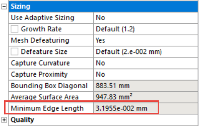
This field provides a read-only indication of the minimum edge length in the model.
Think about the element size that you expect to obtain, especially the desired minimum element size. To help you determine the desired size, in the Geometry window, select the edges of small features that you want to retain and refer to the status bar for feedback about the selections.

Perform a low-effort mesh evaluation by using appropriate sizes as determined from #1, but without controls such as inflation, match mesh controls, and so on, that add constraints to the mesher. Also, try to start with a coarser mesh size and refinement in later steps.
If the mesh is successful, examine it to see whether the mesh size and transition rates are acceptable. In most cases, you will need to make some adjustments to obtain the desired results.
If the mesh fails, examine any messages that the mesher returned to the Messages window, as described elsewhere in this Troubleshooting section.
Adjust settings to retain desired small features:
In many cases, small features are either small holes or channels in the model and are associated with high curvature. For this reason, using the Curvature-based sizing is a good strategy for retaining these features.
Be careful when using Proximity-based sizing. If the value of Minimum Edge Length is too small, using Proximity-based sizing may lead to meshing problems.
Adjust settings to defeature (remove) unimportant small features:
The Meshing application automatically defeatures small features according to the specified Defeature Size. Refer to the Minimum Edge Length value to help determine which small features will be defeatured automatically.
For solid models, Defeature Size is set to 50% of the value of Curvature Min Size by default. If you set a larger Defeature Size, you must also set a larger Curvature Min Size because the defeature size cannot be as large as the minimum element size.
Check the quality with the Quality Histogram and using Display style to view contours and max/min values of metrics such as Skewness, Element Quality and Aspect Ratio. Adjust the mesh settings to achieve the desired quality.
Continue making adjustments until your results are satisfactory. Try adjusting controls such as face sizing, edge sizing, transition rate, and smoothing. You may also want to experiment with virtual topology.
Using a Localized Operating System on Linux
If you are using a localized operating system (such as French or German) on Linux, you must perform additional steps in order for the Meshing application to recognize the correct numerical format. Refer to the platform details section of the Ansys, Inc. Linux Installation Guide for details.
Using Lustre Parallel File Systems on Linux
Meshing application projects created prior to Release 16.0 need to be updated before they can be used on Lustre parallel file systems on Linux. To do this:
Load the project into Release 16 software on a system that does not use a Lustre parallel file system.
Perform an operation that changes each model in the Meshing application (for example, hide and then show a part). If systems share the same model, the change must be done for only one of the systems.
Save the project.


