Once you have built your solid model, established element attributes, and set meshing controls, you are ready to generate the finite element mesh. It is good practice to save your model (SAVE command) before you initiate mesh generation.
You may also want to turn on the "mesh accept/reject" prompt by picking . This feature, which is available only through the GUI, allows you to easily discard an undesirable mesh. (For more information, see Changing the Mesh.)
If you are meshing multiple volumes or areas at one time, you should consider using the meshing option (or issuing the MOPT,ORDER,ON command) so the mesh is created in the smallest volume or area first. This helps ensure that your mesh is adequately dense in smaller volumes or areas and that the mesh is of a higher quality.
To mesh the model, you must use a meshing operation that is appropriate for the entity type being meshed. You can mesh keypoints, lines, areas, and volumes using the commands and GUI paths described below.
Also see Generating a Beam Mesh With Orientation Nodes for information about special beam meshing procedures.
If you need to mesh multiple areas at one time, you should consider issuing the MOPT,ORDER,ON command so the mesh is created in the smallest area first. This helps ensure that your mesh is adequately dense in smaller areas and that the mesh is of a higher quality.
Also see Generating a Volume Mesh From Facets and Generating a Volume Mesh By Sweeping for information about special volume meshing procedures.
Also see Generating an Interface Mesh for Gasket Simulations for information about special gasket meshing procedures.
You can assign orientation keypoints as attributes of a line for beam/pipe meshing, just as you would assign a real constant set number, or a material property set number. The orientation keypoints are independent of the line that is to be meshed. Based on the location of these keypoints, the program will automatically create orientation nodes along with the beam elements. Line meshing with automatic generation of orientation nodes is supported for current-technology elements (such as BEAM188, BEAM189, PIPE288, PIPE289, and ELBOW290).
To assign orientation keypoints as attributes of a line, use the LATT command.
If a line is bounded by two keypoints (KP1 and KP2) and two orientation
keypoints (KB and KE) have
also been defined as attributes of the line, the orientation vector at the
beginning of the line extends from KP1 to KB, and the
orientation vector at the end of the line extends from KP2 to
KE. The program computes the orientation nodes by
interpolating the orientation as given by the above two orientation
vectors.
Note: Although this discussion refers to them as "orientation nodes," elsewhere you may see this type of node referred to as an off-node, third node (for linear beam elements only), or fourth node (for quadratic beam elements only).
The direction in which beam sections are oriented will affect the beam element mesh and the analysis results. Beam meshing with orientation nodes gives you control over these effects. Examples of Beam Meshing With Orientation Nodes provides examples of various ways to align the beam sections.
If your analysis uses current-technology beam, pipe or elbow elements, you can use the cross-section data-definition, analysis, and visualization capabilities for these elements. You can assign a section ID number as an attribute of a line (LATT). The section ID number identifies the cross section used by the beam elements that will be generated when you mesh the line. The orientation nodes, generated automatically based on orientation keypoints that you specify (LATT), determine the section orientations for the beam elements. For detailed information about beam analysis and cross sections, see Beam and Pipe Cross Sections in the Structural Analysis Guide.
This section describes how to generate a beam mesh with orientation nodes, using either command input or the GUI. It assumes that you have already defined the geometry and element attribute tables for your model, and you are now ready to assign specific attributes to a line for beam meshing. This section does not attempt to cover other aspects of a typical beam analysis. For detailed information about beam analysis and a sample problem illustrating the generation of a beam mesh with orientation nodes, see Beam and Pipe Cross Sections in the Structural Analysis Guide.
If you are using the command method to generate the beam mesh, include these commands in your input:
Use the LSEL command to select the lines that you want to mesh with orientation nodes.
Use the LATT command to associate element attributes with the selected, unmeshed line(s). Specify values for the MAT, REAL, TYPE, ESYS, KB, KE, and SECNUM arguments.
When specifying a value for the TYPE argument on the LATT command, be sure that the element type you assign to the line is one that supports beam meshing with orientation (current-technology beam, pipe or elbow elements).
Use the KB and KE arguments on the LATT command to assign beginning and ending orientation keypoints. If you are meshing with current-technology beam elements, you must define at least one orientation keypoint when you set your attributes for meshing. When the mesh generates (LMESH), each beam element along the line will have two end nodes and one orientation node.
If you are meshing a circular arc with beams, and if that arc spans more than 90°, the beam orientation is twisted at the 90° point as shown in Figure 7.31: LMESH of an Arc:
To prevent the beam orientation from twisting, set the ending orientation keypoint (KE) to be the same as KB, or split the line into 90° arcs.
If you are using current-technology beam, pipe or elbow elements, use the
SECNUMargument on the LATT command to assign a section ID number.
See Examples of Beam Meshing With Orientation Nodes for examples that illustrate various ways of assigning orientation keypoints. See Beam and Pipe Cross Sections in the Structural Analysis Guide for details about cross sections.
Set the number of element divisions to be generated along the line mesh (LESIZE).
Use the LMESH command to mesh the line(s).
After meshing a beam, always use the /ESHAPE,1 command to verify the beam's orientation graphically.
You can use the LLIST,,,,ORIENT command to list the selected line(s), along with any assigned orientation keypoints and section data.
You can define one orientation keypoint or two orientation keypoints as attributes of a line. If you define two, you can assign both of them to the same location in your model.
Figure 7.32: Placement of Orientation Keypoints and Element Orientation shows three examples. For each example, a beginning orientation keypoint and an ending orientation keypoint have been defined at the same location. The examples illustrate how you can assign different orientation keypoints to align selected beam sections within a structure in different directions.
If you specify one orientation keypoint for a line, the program generates beam elements along the line with a constant orientation. If you specify different orientation keypoints at each end of the line, the program generates a pre-twisted beam.
Figure 7.33: Constant Orientation vs. Pre-Twist illustrates some differences between beam meshing with constant orientation as opposed to beam meshing with pre-twist.
In Figure (a), only a beginning orientation keypoint was assigned. The keypoint is 0° from the y axis at a distance of 10 units in the y direction. The beam exhibits constant orientation.
In Figure (b), only a beginning orientation keypoint was assigned. The keypoint is 30° from the y axis at a radius of 10 units. The beam exhibits constant orientation.
In Figure (c), both a beginning and an ending orientation keypoint were assigned. The keypoints are 90° apart, causing a 90° twist in the beam. Due to the linear interpolation that is used to determine the location of the orientation nodes, a line biasing with small divisions at each end was used to cause the nodes to be located closer to the vectors made by the keypoints.
In Figure (d), the orientation keypoints are 180° apart, and this time the beam flips. Assigning these keypoints causes a discontinuity because the interpolation of the two vectors is linear.
Figure (e) provides a remedy to the problem illustrated in Figure (d). Here one line was divided into two, with the ending orientation keypoint for L1 and the beginning orientation keypoint for L2 being assigned to the same keypoint. A 180° twist is achieved.
Other things to consider when meshing beams with orientation nodes include the following:
Since orientation is not required for 2D beam elements, the beam meshing procedure described in this section does not support 2D beam elements.
Any operation on a line (copying the line, moving the line, and so on) will destroy the keypoint attributes.
If an orientation keypoint is deleted, the program issues a warning message.
If an orientation keypoint is moved, it remains an orientation keypoint. However, if an orientation keypoint is redefined (K,
NPT,X,Y,Z), the program no longer recognizes it as an orientation keypoint.
Caution: If you issue the CDWRITE command after generating a beam mesh with orientation nodes, the database file will contain all of the nodes for every beam element, including the orientation nodes. However, the orientation keypoints that were specified for the line (LATT) are no longer associated with the line and are not written out to the geometry file. The line does not recognize that orientation keypoints were ever assigned to it, and the orientation keypoints do not "know" that they are orientation keypoints. Thus, the CDWRITE command does not support (for beam meshing) any operation that relies on solid model associativity. For example, meshing the areas adjacent to the meshed line, plotting the line that contains orientation nodes, or clearing the line that contains orientation nodes may not work as expected. This limitation also exists for the IGESOUT command. See the descriptions of the CDWRITE and IGESOUT commands for more information.
In addition to using VMESH to generate volume elements, you can generate a volume mesh from a set of detached exterior area elements (facets). For example, this capability is useful in situations where you cannot mesh a particular area. In such a situation, first mesh the areas that can be meshed. Next, define the remaining area elements using direct generation. (Elements that you define using direct generation are considered to be detached elements, because they have no solid model associativity.) Finally, use the FVMESH command to generate nodes and tetrahedral volume elements from the detached area elements.
Note: The main tetrahedra mesher (MOPT,VMESH,MAIN) is the only tetrahedra mesher that supports the generation of a volume mesh from facets. The alternate tetrahedra mesher (MOPT,VMESH,ALTERNATE) does not.
Note: The FVMESH command and its corresponding menu path do not support multiple "volumes." If you have multiple volumes in your model, select the surface elements for one "volume," while making sure that the surface elements for the other volumes are deselected. Then use FVMESH to generate a mesh for the first volume. Continue this procedure by selecting one volume at a time and meshing it, until all of the volumes in the model have been meshed.
Additional considerations for using xMESH commands include the following:
Sometimes you may need to mesh the solid model with a variety of elements of different dimensionalities. For example, you may need to "reinforce" a shell model (area elements) with beams (line elements), or overlay one of the faces of a 3D solid model (volume elements) with surface effect (area) elements. You can do so by using the appropriate meshing operations (KMESH, LMESH, AMESH, and VMESH) in any desired order. Make sure, however, that you set the appropriate element attributes (discussed earlier in this chapter) before meshing.
No matter which volume mesher you choose (MOPT,VMESH,
Value), it may produce different meshes on different hardware platforms when meshing volumes with tetrahedral elements (VMESH, FVMESH). Therefore, you should be cautious when evaluating results at a specific node or element. The location of these entities may change if the input created on one platform is later run on a different platform.
Using volume sweeping, you can fill an existing unmeshed volume with elements by sweeping the mesh from a bounding area (called the "source area") throughout the volume. If the source area mesh consists of quadrilateral elements, the volume is filled with hexahedral elements. If the area consists of triangles, the volume is filled with wedges. If the area consists of a combination of quadrilateral and triangular elements, the volume is filled with a combination of hexahedral and wedge elements. The swept mesh is fully associated with the volume.
Volume sweeping provides these benefits:
Unlike other methods for extruding a meshed area into a meshed volume (VROTAT, VEXT, VOFFST, and VDRAG commands), volume sweeping (VSWEEP) is intended for use in existing unmeshed volumes. Thus it is particularly useful in these situations:
You have imported a solid model that was created in another program, and you want to mesh it in this one.
You want to create a hexahedral mesh for an irregular volume. You only have to break up the volume into a series of discrete sweepable regions.
You either want to create a different mesh than the one that was created by one of the other extrusion methods, or you forgot to create a mesh during one of those operations.
If you do not mesh the source area prior to volume sweeping, the program meshes it for you when you invoke the volume sweeper. The other extrusion methods require you to mesh the area yourself before you invoke them. If you do not, the other extrusion methods create the volume, but no area or volume mesh is generated.
Follow these steps before you invoke the volume sweeper:
Determine how many volumes need to be swept by VSWEEP. VSWEEP will sweep either a single volume, all selected volumes (VSWEEP,ALL) or a component of volumes (VSWEEP,CMVL where CMVL is the name of a volume component.)
Determine whether the volume's topology can be swept. The volume cannot be swept if any of these statements is true:
If LESIZE is used with the "hard" option, and the source and target areas contain hard division which are the not the same for each respective line, then the volume is not sweepable.
The volume contains more than one shell. In other words, there is an internal void within the volume. (A shell is the volumetric equivalent of an area loop - a set of entities that defines a continuous closed boundary. The SHELL column in a volume listing (VLIST) indicates the number of shells in the volume.)
The source area and the target area are not opposite one another in the volume's topology. (By definition, the target area must be opposite the source area.)
There is a hole in the volume that does not penetrate the source and/or target areas.
Note: Even if you have satisfied these requirements, there may be times when the shape of a volume causes the volume sweeper to create poorly shaped elements. For help, see Strategies for Avoiding Shape Failures During Volume Sweeping.
If the volume is not sweepable, try to cut the volume into sweepable sub-volumes before using the VSWEEP command.
Make sure that you have defined the appropriate 2D and 3D element types (ET). For example, if you are going to pre-mesh the source area, and you want the swept volume to contain quadratic hexahedral elements, you should mesh the source area with quadratic 2D elements.
Determine how you want to control the number of element layers that will be created during the sweeping operation. That is, the number of elements that will be created along the length of the sweep direction (see Figure 7.34: Specifying Volume Sweeping). You can use any of these methods to control this number:
Use ESIZE,SIZE to specify a guiding element size for the sweeper. VSWEEP uses this value to internally compute the number of element layers. This is the preferred method for setting this value.
Use the EXTOPT,ESIZE,
Val1,Val2command to specify the number of element layers (and if desired, the spacing ratio or bias) to be used along the volume's side lines (whereVal1is the number of element layers andVal2is the bias). Note that the number of element layers and bias that you specify with EXTOPT will apply to all of the volume's unmeshed side lines. For any side line that has been pre-meshed or that has other sizing specifications associated with it (via LESIZE), the values set by EXTOPT are ignored.On one or more of the volume's side lines, use the LESIZE command to specify the number of element divisions for that particular line. This method also permits you to specify a bias that the volume sweeper will honor (LESIZE,,,,,
SPACE). However, the bias applies only to the line that you identify on the LESIZE command.Generate a mapped mesh on one or more of the side areas or within a volume or area that is adjacent to a side area or side line.
Generate a mesh of beam elements on one or more of the side lines (LMESH).
Turn on Smart sizing (via SMRT). VSWEEP will use smart sizing parameters to internally compute the number of element layers. Note that because of the constrained nature of Hexahedral Elements, and because smart sizing attempts to transition element sizes in different regions of the model, smart sizing does not always yield the highest quality elements. Although using the ESIZE,SIZE method mentioned above usually generates more elements, for Hex meshing they will normally be higher quality.
If the number of element layers is not specified with one of the methods listed above, VSWEEP will use DESIZE parameters to internally compute it.
Optionally, determine which of the areas bounding the volume will be the source area, and which will be the target area. The program uses the pattern of the area elements on the source area (which can be quadrilateral and/or triangular elements) to fill the volume with hexahedral and/or wedge elements. (If you have not pre-meshed the area prior to volume sweeping, the program automatically generates "temporary" area elements. It does not save these area elements in the database. They are discarded as soon as the pattern for the swept volume is determined.) The target area is simply the area that is opposite the source area. See Figure 7.34: Specifying Volume Sweeping above, which illustrates one way that a user might set the number of element layers, source area, and target area for a volume sweeping operation. If more than one volume is being swept any user specified source and targets are ignored.
If no source and/or target area(s) are specified by the user, VSWEEP will attempt to automatically determine which bounding areas should be used as the source or target. If VSWEEP cannot determine the source/target automatically, VSWEEP will stop. When using the GUI, you can turn on auto source and target detection with the EXTOPT,VSWE,AUTO command.
Optionally, mesh the source, target, and/or side area(s).
The results of a volume sweeping operation will differ depending on whether you have meshed any of the areas (source, target, and/or side areas) in your model prior to sweeping.
Typically, you will generate a mesh for the source area yourself, before you sweep the volume. If you have not meshed the source area, the program will mesh it internally when you invoke the volume sweeping operation (as described above in Step 4.
Consider the following information when deciding whether to "pre-mesh" before sweeping:
If you do not pre-mesh, the program uses the element shape setting (MSHAPE) to determine the element shape it uses to mesh the source area. (MSHAPE,0,2D results in quadrilateral elements. MSHAPE,1,2D results in triangular elements.) The exception to this is if you sweep multiple volumes with a single call to VSWEEP. In this case the source area is always meshed with quadrilaterals.
If you want the source area meshed with a KSCON specification, pre-mesh the source area.
The sweeping operation will fail if hard points are present on an area or line that is associated with the volume, unless you pre-mesh the area or line containing the hard point.
If you pre-mesh both the source area and the target area, the area meshes must match. However, the source area mesh and the target area mesh do not have to be mapped meshes.
See Other Characteristics of Volume Sweeping for more information about the characteristics of the volume sweeping feature.
Figure 7.35: Sweeping Adjacent Volumes (a) shows an example of a model that contains two volumes adjacent to one another. Because of the model's geometry, it is necessary to sweep the volumes in different directions, as shown in Figure (b).
To invoke the volume sweeper, issue the
VSWEEP,VNUM,SRCA,TRGA,LSMO
command. Specify values for the following arguments:
Use the
VNUMargument to identify the volume or volumes that you want to sweep.Optionally, use the
SRCAargument to identify the source area.Optionally, use the
TRGAargument to identify the target area.Optionally, use the
LSMOargument to specify whether the program should perform line smoothing during the sweeping operation.
See the description of the VSWEEP command for more information about these arguments.
Note: When using the GUI to sweep a volume, you cannot control whether line smoothing occurs. The program does not perform line smoothing when volume sweeping is invoked from the GUI.
If a volume sweeping operation fails due to bad element shapes, try one or more of the strategies listed below. Ansys recommends that you try these strategies in the order in which they are listed. Hereafter in this section, all references to a figure are specific to Figure 7.36: Strategies for Avoiding Stretched Elements.
If you did not specify a source and target, specify them and try the volume sweeper again.
Switch the source and target areas and re-invoke the volume sweeper. For example, if you specify area A1 as your source area and area A2 as your target area, and the sweep operation fails, try again using A2 as the source area and A1 as the target area.
Choose an entirely different set of source and target areas and re-invoke the volume sweeper. (Some volumes can be swept in more than one direction.) For example, if area A1 and area A2 do not work, try using A5 and A6.
Use shape checking as a diagnostic tool to determine which region of the model is causing the sweep failure. To do this, reduce the shape checking level to warning mode (SHPP,WARN), so that elements that violate error limits result in warning messages rather than element failures. Then re-invoke the sweeping operation. Use the resulting warning messages to identify the region of the model that contains the bad elements, and then clear the bad element mesh (VCLEAR). Turn shape checking back on (SHPP,ON). Next, modify the region of the model that contained the bad elements. Finally, mesh the volume again with a subsequent sweep operation. Here are some suggestions for modifying the model:
If one of the lines in the region of poor elements appears to have too many or too few divisions, manually specify a different number of divisions for that line using LESIZE.
Try using a smaller element size specification (ESIZE,SIZE) or a different number of element layers.
Divide the volume into two or more volumes (VSBA,VSBW), which will shorten the length of the sweep direction. Try dividing the volume near the region where the poorly shaped elements occur. Afterwards, invoke VSWEEP for each of the resulting volumes.
If the elements flagged by SHPP,WARN appear to be stretched within thin sections of the target area as in Figure (c), try dividing the side areas in that region along the direction of the sweep. Use these steps:
Clear the mesh (VCLEAR).
Divide one of the lines on the source area and one of the lines on the target area by adding keypoints at the desired division locations (LDIV). See Figure (e).
Copy the line divisions from the new lines on the source area to the corresponding new lines on the target area as described in Figure (e). (The "new lines" are those that were created by Step 2.) You can copy line divisions easily via the MeshTool. Choose menu path . On the MeshTool, press the Copy button to open the picker. Use the picker to copy the line divisions - including spacing ratios - from one line to the other.
Manually map mesh the side area that was affected by Step 2. See Figure (f).
Re-invoke the volume sweeper.
If the elements flagged by SHPP,WARN are stretched within thin sections of the target area, but the previous strategy does not work, clear the mesh and then re-invoke the volume sweeper with line smoothing turned on (VSWEEP,,,,1). See Figure (d). (This setting is not recommended for large models due to speed considerations.)
Figure (c), (d), and (g) show the results of three different sweeping operations. They illustrate how you can use some of the strategies described above to affect the quality of a swept mesh. All three cases started with the same volume, which is shown in Figure (a). Figure (b) illustrates the source mesh that was used during the sweep. Again, in all three cases, this source mesh was generated prior to invoking volume sweeping.
The differences in the results are due to the additional actions (if any) taken prior to sweeping. Figure (c) shows the results of invoking volume sweeping without using any of the strategies described above. Notice the stretched elements that appear on the target area. Figure (d) shows the results of invoking volume sweeping with line smoothing turned on (VSWEEP,,,,1). In this case, the element shapes are better than those shown in Figure (c). However, they are not as good as those shown in Figure (g). This example shows the results of dividing lines (LDIV) on the source and target area and map meshing the affected side area prior to sweeping. Notice the significant improvement in the shape of the elements on the target area in Figure (g).
Other characteristics of volume sweeping include the following:
The source area and the target area do not have to be flat or parallel.
If the topology of the source area and the topology of the target area are the same, the sweeping operation will often succeed even if the shape of the source area is different from the shape of the target area. However, drastically different shapes can cause element shape failures.
During volume sweeping, the program can create either linear or quadratic elements. It can sweep quadratic area elements into linear volume elements, and it can sweep linear area elements into quadratic volume elements. (However, when the program sweeps linear area elements into quadratic volume elements, mid-nodes are not added to the edges of the source area. This will result in an element shape failure if you are using quadratic volume elements that do not support dropped mid-nodes.)
If no source and target is provided, any values specified EXTOPT, ESIZE, NDIV, BIAS are ignored because they are direction dependent.
If you have pre-meshed the source, target, and/or side areas, you can issue the EXTOPT,ACLEAR,1 command prior to sweeping and the program will automatically clear the area elements from any selected source, target, or side area after the swept volume mesh is created. The areas that you want to clear must be selected for clearing of the area meshes to occur.
Volume sweeping does not require your model to have a constant cross section. However, if the cross section varies, it should vary linearly from one end of the sweep to the other for best results.
During volume sweeping, if you do not pre-mesh the source area, the program will use the SMRTSIZE, KESIZE, ESIZE, or DESIZE command setting (as appropriate) to mesh the source area. Also note the following information about the ESIZE command. The ESIZE,,
NDIVsetting may be used to determine the number of element layers that will be created along the volume's side lines during sweeping. However, this is not the preferred method because if the source area is not pre-meshed, the number of element divisions specified byNDIVwill apply to all of the source area lines as well. If you want a specified number of element layers, the preferred method is to use the EXTOPT command (as described earlier).VSWEEP can sweep about a zero radius axis (that is, the source and target areas are adjacent) if you specify which areas are to be used as the source and target (see figure below).
If you do not specify a source and target on a volume requiring a zero radius axis, VSWEEP will not succeed. In addition, the element type used by VSWEEP must support wedges if sweeping a quad mesh and pyramids and tets if sweeping a tri mesh. You cannot perform a sweep about a zero-radius axis on defeaturable models.
You must generate an interface mesh as part of the overall meshing procedure for simulating a gasket joint. This type of simulation involves using one of the 2D or 3D linear or quadratic interface elements layered between structural elements that have the same characteristics. Meshing of the interface element is done through the IMESH command for the gasket layer, and meshing of the structural elements is done through either the AMESH or VMESH command. The specific order of the meshing procedure is shown below, in reference to the following figure:
Define interface and structural elements that have corresponding characteristics. See Element Selection in the Structural Analysis Guide for element selection guidelines.
Mesh the structural component element that contains the source face using either the AMESH or VMESH command.
Mesh the gasket layer component element using either IMESH,LINE or IMESH,AREA, or VDRAG.
Mesh the structural component element that contains the target face using either the AMESH or VMESH command.
See the Notes sections of the IMESH, VDRAG, and EGEN command descriptions for special gasket meshing requirements.
Also, see Meshing Interface Elements in the Structural Analysis Guide for a sample input listing that includes the IMESH command plus graphics that represent various meshes of interface and structural elements.
When meshing is initiated, a status window appears. The window displays a message concerning the current status of the meshing operation, and also displays a scale showing the percentage of the meshing operation that is complete. Both the message and the percentage scale are updated periodically as the operation proceeds.
A STOP button is located at the bottom of the status window. Click STOP to abort the mesh operation. Incomplete meshes are discarded. Areas or volumes that were completely meshed before you clicked STOP are retained. The solid model and finite element model are left as they were before meshing was initiated.
You will see the meshing status window only when working in GUI mode. (Status windows will appear by default, but can be turned off by issuing /UIS,ABORT,OFF.)
In non-GUI mode, a mesh abort is triggered by the system "break" function (Ctrl+C or Ctrl+P on most systems).
Note: If a session log file (Jobname.log) from an interactive session that included an intentional mesh abort is used as input for another session, the results will not likely be the same as they were for the interactive session since the abort will not be reproduced in the subsequent runs.
"Badly shaped" elements can, on occasion, cause very poor analytical results. For this reason, the program performs element shape checking to warn you whenever any operation creates an element having a poor shape. Unfortunately, however, there are few universal criteria that can be used to identify a "poorly shaped" element. In other words, an element that gives poor results in one analysis might give perfectly acceptable results in another analysis. Thus, you must realize that the criteria that the program uses to identify poor element shapes are somewhat arbitrary. The fact that you receive even hundreds of element shape warnings does not necessarily mean that element shapes will cause any inaccuracy of results. (Conversely, if you do not receive any warnings about element shapes, that does not guarantee accurate results.) As in so many aspects of finite element analysis, the final determination of whether or not your element shapes are acceptable for your application remains your responsibility.
The program detects and flags all element shape warning and error conditions at the time of element creation, before storing each element.
Although the program performs element shape checking by default, a number of options for controlling element shape checking are available. Usse the SHPP command to modify shape checking. Most of the SHPP options are described in the sections that follow. See the description of the SHPP command for additional information.
The sections that follow cover how to:
Turn element shape checking off entirely or to warning-only mode
Turn individual shape tests off and on
View a summary of shape test results
View current shape parameter limits
Change shape parameter limits
Retrieve element shape parameter data
Understand the circumstances under which the program retests existing elements, and why doing so is necessary
Decide whether element shapes are acceptable
Caution: The existence of badly shaped elements in a model may lead to certain computational errors that can cause your system to abort during solution. Therefore, you run the risk of a system abort during solution any time that you turn element shape checking off entirely, run shape checking in warning-only mode, turn off individual shape checks, or loosen shape parameter limits.
Note: The Mechanical APDL Theory Reference provides detailed information about the shape tests that the program performs and explains the logic that was used to determine each test's default warning and error limits.
As stated above, the program performs element shape checking by default. When element shape checking occurs, any new element - regardless of how it was created - is tested against existing shape parameter warning and error limits. If the element violates any of the error limits, it not only produces an error message, but also either (a) causes a meshing failure, or (b) for element creation other than AMESH or VMESH, is not stored.
In certain cases, it may be desirable to turn element shape checking off, or to turn it on in warning-only mode. Turning element shape checking off (SHPP,OFF,ALL) deactivates shape checking entirely. When element shape checking is turned on in warning-only mode (SHPP,WARN), shape checking occurs, but elements that violate error limits now only give warnings and do not cause either a meshing or element storage failure.
Situations in which Ansys recommends that you turn shape checking off or run it in warning-only mode include:
When you are generating an area mesh (AMESH), but your ultimate intention is to generate a volume mesh (VMESH) of quadratic tetrahedrons with that area as one of the volume's faces. Note that the tetrahedra mesher can fix meshes in which area elements have poor Jacobian ratios. Therefore, if you are generating an area mesh for an area that will be a face on a volume in a subsequent volume meshing operation, it may make sense to turn element shape checking to warning-only mode, mesh the area, turn element shape checking on, and then mesh the volume.
When you are importing a mesh (CDREAD). If "bad" elements exist in a mesh that you want to import and element shape checking is turned on, the program may bring the mesh into the database with "holes" where the bad elements should be (or it may not import the mesh at all). Since neither of these outcomes is desirable, you may want to turn element shape checking either off or to warning-only mode prior to importing a mesh. After you import, we suggest that you turn shape checking back on and recheck the elements (CHECK,ESEL,WARN or CHECK,ESEL,ERR).
Note: Once elements are in the database, performing element shape checking will not delete them. If any elements in violation of error limits are selected when you initiate a solution (SOLVE), the program issues an error message and does not process the solution.
When you are using direct generation and you are creating elements that you know will be temporarily invalid. For example, you may be creating a wedge-shaped element that has coincident nodes. You know that you need to merge the coincident nodes (NUMMRG) in order to get valid elements. In this case, it would make sense to turn off element shape checking, complete the desired operations (such as merging nodes in this example), turn element shape checking on, and then check the elements for completeness (CHECK).
Rather than turn off shape checking entirely, you can selectively control which tests are off and which are on.
To use the command method to toggle the tests off and on, issue the command
SHPP,Lab,VALUE1:
Use the
Labargument to indicate whether you want to turn tests off or on. Specify OFF to turn tests off. Specify ON to turn tests on.Use the
VALUE1argument to indicate which tests you want to turn off or on. You can specify ASPECT (aspect ratio tests), PARAL (deviation from parallelism of opposite edges tests), MAXANG (maximum corner angle tests), JACRAT (Jacobian ratio tests), or WARP (warping factor tests). You can also specify ALL to turn all tests off or on.
For example, the command SHPP,OFF,WARP turns off all warping factor tests.
The output below is from the SHPP,SUMMARY command. It provides a summary of shape test results for all selected elements.
SUMMARIZE SHAPE TESTING FOR ALL SELECTED ELEMENTS

 ------------------------------------------------------------------------------
            <<<<<<          SHAPE TESTING SUMMARY           >>>>>>
            <<<<<<        FOR ALL SELECTED ELEMENTS         >>>>>>
 ------------------------------------------------------------------------------
                    --------------------------------------
                    |  Element count       214 PLANE183   |
                    --------------------------------------

  Test                Number tested  Warning count  Error count    Warn+Err %
  ----                -------------  -------------  -----------    ----------
  Aspect Ratio                214              0             0         0.00 %
  Maximum Angle               214             59             0        27.57 %
  Jacobian Ratio              214              0             0         0.00 %

  Any                         214             59             0        27.57 %
------------------------------------------------------------------------------The output below is from the SHPP,STATUS command. It lists the element shape parameters and default shape parameter limits. By default, when an element's shape falls outside of these limits, a warning or error condition occurs. See Changing Shape Parameter Limits for information about how to change the limits.
This output shows the default shape parameter limits. If you modify any of these limits or turn off any of the individual shape tests, your output will differ accordingly.
In most cases in the output below, "FACE" also means "cross-section of solid element." For example, the ASPECT RATIO limits apply to both faces and cross-sections of tetrahedra, hexahedra (bricks), pyramids, and wedges.
 ASPECT RATIO (EXCEPT EMAG)
    QUAD OR TRIANGLE ELEMENT OR FACE
         WARNING TOLERANCE ( 1) =   20.00000
         ERROR TOLERANCE   ( 2) =   1000000.
 DEVIATION FROM PARALLEL OPPOSITE EDGES IN DEGREES    (EXCEPT EMAG)
    QUAD ELEMENT OR FACE WITHOUT MIDSIDE NODES
         WARNING TOLERANCE (11) =   70.00000
         ERROR TOLERANCE   (12) =   150.0000
    QUAD OR QUAD FACE WITH MIDSIDE NODES
         WARNING TOLERANCE (13) =   100.0000
         ERROR TOLERANCE   (14) =   170.0000
 MAXIMUM CORNER ANGLE IN DEGREES (EXCEPT EMAG)
    TRIANGLE ELEMENT OR FACE
         WARNING TOLERANCE (15) =   165.0000
         ERROR TOLERANCE   (16) =   179.9000
    QUAD ELEMENT OR FACE WITHOUT MIDSIDE NODES
         WARNING TOLERANCE (17) =   155.0000
         ERROR TOLERANCE   (18) =   179.9000
    QUAD ELEMENT OR FACE WITH MIDSIDE NODES
         WARNING TOLERANCE (19) =   165.0000
         ERROR TOLERANCE   (20) =   179.9000
 JACOBIAN RATIO
    h-METHOD ELEMENT
         WARNING TOLERANCE (31) =   30.00000
         ERROR TOLERANCE   (32) =   1000.000
    QUAD ELEMENT OR FACE WARPING FACTOR
    SHELL181
         WARNING TOLERANCE (51) =   1.000000
         ERROR TOLERANCE   (52) =   5.000000
    INFIN47, INTER115, SHELL131, SHELL157,
    SHELL181 WITH NLGEOM OFF AND KEYOPT1 NOT = 1
         WARNING TOLERANCE (53) =  0.1000000
         ERROR TOLERANCE   (54) =   1.000000
    SHELL181 WITH KEYOPT1=1
         WARNING TOLERANCE (55) =  0.4000000E-04
         ERROR TOLERANCE   (56) =  0.4000000E-01
    SHELL181 WITH NLGEOM ON AND KEYOPT1 NOT = 1
         WARNING TOLERANCE (59) =  0.1000000E-04
         ERROR TOLERANCE   (60) =  0.1000000E-01
    3D SOLID ELEMENT FACE
         WARNING TOLERANCE (67) =  0.2000000
         ERROR TOLERANCE   (68) =  0.4000000
ELEMENT SHAPE CHECKING IS ON WITH DEFAULT LIMITS
If the default shape parameter limits do not suit your
purposes, you can change them by using the command
SHPP,MODIFY,VALUE1,VALUE2.
See the description of the SHPP command for more
information.
The element shape checking controls provide the flexibility to fit varied analysis needs. For example, perhaps you are not particularly concerned about aspect ratio measures. You can turn off all aspect ratio testing by including the command SHPP,OFF,ASPECT in your start.ans file. If that seems too drastic for your situation, you may choose to specify SHPP,MODIFY,1,1000 instead. Doing so radically loosens the warning limit for aspect ratio tests, without turning off the tests entirely:
You can use the *GET and *VGET commands to retrieve element shape parameter data:
For example, the command *GET,A,ELEM,3,SHPAR,ASPE returns the calculated aspect ratio of element number 3 and stores it in a parameter named A. The command *VGET,A(1),ELEM,3,SHPAR,ASPE returns the aspect ratio of element number 3 and stores it in the first location of A. Retrieval continues with elements numbered 4, 5, 6, and so on, until successive array locations are filled.
See the descriptions of the *GET and *VGET commands in the Command Reference for more information.
Certain types of changes that you make to defined elements can invalidate prior element shape testing. The program generally traps these types of changes and retest the affected elements automatically. Circumstances under which the program retests existing elements include:
When you change the element type (ET,,
Enameor ETCHG,Cnv) or one of its key options (KEYOPT).When you change the element TYPE number of an element (EMODIF).
When you change the large deformation key (NLGEOM,
Key) for SHELL181 elements.When you define a shell thickness (R) after you define an element, or you change an existing shell thickness (RMODIF) or the REAL number of a shell element (EMODIF).
Element type and TYPE number — There is a distinction between the element type and that element type's TYPE number. The element type is the true name of the element (for example, SHELL181, sometimes shortened to simply 181). The element type's TYPE number is an arbitrary number that is locally assigned to a particular element type. Use the TYPE number to reference the element type when assigning attributes to your model.
Here are some suggestions to help you decide whether you should be concerned about an element shape warning:
Never ignore an element shape warning. Always investigate the effect that a "poorly" shaped element might have on your analysis results.
Recognize that structural stress analyses that have the goal of determining stress at particular locations will typically suffer more severe effects from "poorly" shaped elements than will other types of analyses (deflection or nominal stress, modal, thermal, magnetic, etc.).
If any "poorly" shaped elements are located in a critical region (such as near a critical stress point), their effect is more likely to be detrimental.
"Poorly" shaped higher-order (midside-node) elements will generally produce better results than will similarly shaped linear elements. The default shape parameter limits are more restrictive on linear elements than on higher-order elements.
Verification of analysis results by comparison with other analyses, test data, or hand calculations is essential regardless of whether elements produce shape warnings. If such verification indicates that you have high-quality results, there is little reason to worry about shape warnings.
Some of the best quantitative measures of an element's acceptability are the error measures based on the element-to-element discontinuity in a stress or thermal gradient field. (See The General Postprocessor (POST1) in the Basic Analysis Guide. An element that produces shape warnings and shows a high error measure compared to its neighbors is suspect.)
To check element shapes in an existing mesh (an internally created mesh or an imported mesh), use the CHECK command.
See the description of the SHPP command for more information about element shape checking.
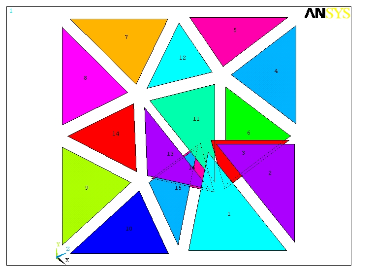
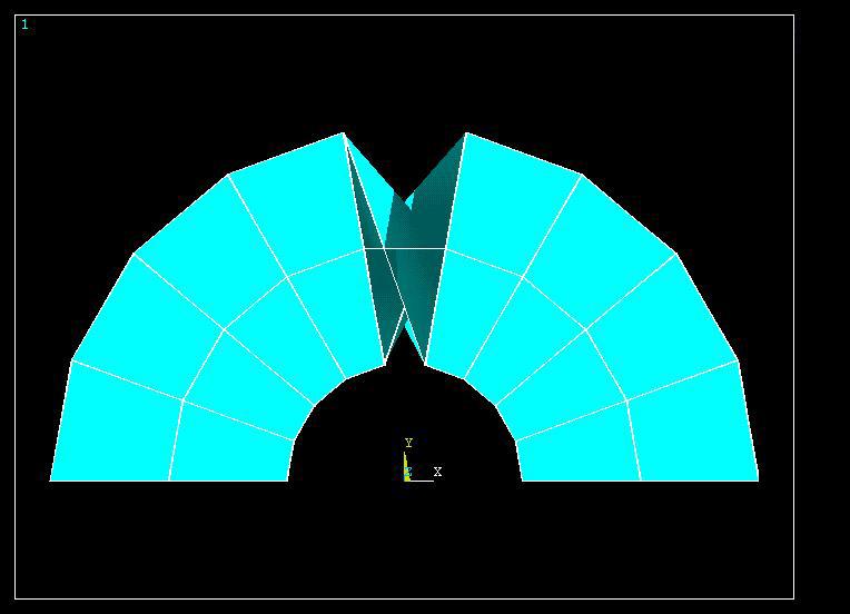
There are times when the CHECK command will fail to detect potential problems in a mesh. The CHECK command is designed to examine each individual selected element and report warnings or errors based on specified shape criteria. It will not detect overlapping or poorly-connected elements. The MCHECK command is designed to detect potential problems with how elements are connected to each other. Figure 7.39: Flawed Mesh (elements "folded") shows an example of a flawed mesh that would not be detected by the CHECK command. All elements in this mesh are of acceptable quality. The MCHECK command, however, would detect the potential connectivity problem and report an error.
The MCHECK command will perform a number of validity checks on the selected elements, including
| 1. Normal check: Wherever two area elements share a common edge, MCHECK verifies that the ordering of the nodes on each element is consistent with their relative normals. |
| 2. Volume check: Wherever two volume elements share a common face, MCHECK verifies that the sign of the integrated volume of each element is consistent. |
| 3. Closed surface check: MCHECK verifies that the element exterior faces form simply-connected closed surfaces (this may detect unintended cracks in a mesh). |
| 4. Check for holes in the mesh: MCHECK warns if the number of element faces surrounding an interior void in the mesh is small enough to suggest one or more accidentally omitted elements, rather than a deliberately formed hole. For this test, the number of faces around the void is compared to the smaller of a) three times the number of faces on one element, or b) one-tenth the total number of element faces in the model. |
To check mesh connectivity, use the
MCHECK,Lab command. Like the
CHECK command, MCHECK gives the option to
unselect all valid elements. You can then visually identify any potential problem
elements. Use MCHECK
Lab=ESEL to unselect valid elements.