


Check Mesh Quality determines how the software behaves with respect to error and warning limits:
Yes, Errors (default) - If the meshing algorithm cannot generate a mesh that passes all error limits, an error message is printed and meshing fails.
Yes, Errors and Warnings - If the meshing algorithm cannot generate a mesh that passes all error limits, an error message is printed and meshing fails. In addition, if the meshing algorithm cannot generate a mesh that passes all warning (target) limits, a warning message is printed.
No - Mesh quality checks are done at various stages of the meshing process (for example, after surface meshing prior to volume meshing). The No setting turns off most quality checks, but some minimal checking is still done. In addition, even with the No setting, the target quality metrics are still used to improve the mesh. The No setting is intended for troubleshooting and should be used with caution as it could lead to solver failures or incorrect solution results.
Mesh Quality Worksheet: Measures the mesh quality and allows you to set warning and error limits for each mesh quality criterion. When you select Mesh Quality Worksheet, the Display Style contours are modified to display the elements that exceed the warning and error limits.
Note: Changing the Check Mesh Quality setting after you have meshed affects the mesh status as follows:
If, after meshing, you change the Check Mesh Quality setting from No to Yes, Errors or Yes, Errors and Warnings, or you change the setting from Yes, Errors to Yes, Errors and Warnings, the mesh becomes out-of-date and requires action.
If, after meshing, you change the Check Mesh Quality setting from Yes, Errors and Warnings to another setting, or you change the setting from Yes, Errors to No, the mesh will not go out-of-date. However, some old messages may not directly apply anymore.
If, after meshing, you change the Check Mesh Quality setting from No or Yes, Errors or Yes, Errors and Warnings to Mesh Quality Worksheet, it validates the generated mesh.
Mesh Quality Worksheet
Mesh Quality Worksheet helps you to measure the quality of mesh, provide visualization tools for finding areas of low mesh quality and improve the mesh. The Mesh Quality Worksheet displays the quality criteria and its default warning and error limit based on the selected Physics Preference. When you change the Physics Preference, the worksheet metrics column gets reset to the default values. To access Mesh Quality Worksheet, You can click Mesh on the Tree Outline and click Quality Worksheet in the Mesh Context tab on the ribbon. Mesh Quality Worksheet is available for No or Yes, Errors or Yes, Errors and Warnings and Mesh Quality Worksheet in Check Mesh Quality.
Mesh Quality Worksheet options are as follows:
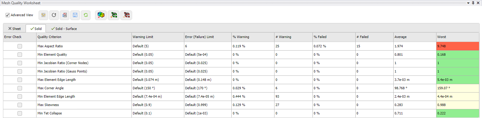
Advanced View: Allows you to have a detailed view of the quality metrics. It displays the %Warning, #Warning, %Failed, #Failed and Average columns when enabled.
 :
Open the Options window to set the mesh metric visibility for
the selected quality criterion in the Mesh Quality Worksheet .
you can use right-click options to select single or multiple quality criterion. The
available right-click options are:
:
Open the Options window to set the mesh metric visibility for
the selected quality criterion in the Mesh Quality Worksheet .
you can use right-click options to select single or multiple quality criterion. The
available right-click options are:
Physics Preference: Sets the default value for quality criterion based on the Physics Preference in the Details view.
On: Enables the quality criterion visibility in the Mesh Quality Worksheet for the selected mesh metric.
Off: Disables the quality criterion visibility in the Mesh Quality Worksheet for the selected mesh metric.
 :
Allows you to reset the worksheet warning and error limit values to default ones.
:
Allows you to reset the worksheet warning and error limit values to default ones.
 : Allows you to load
or resume the saved mesh quality worksheet by reading a *.csv file.
: Allows you to load
or resume the saved mesh quality worksheet by reading a *.csv file.
 : Allows you to save
the mesh quality worksheet in *.csv format.
: Allows you to save
the mesh quality worksheet in *.csv format.
 : Allow you to
change the errors or warning limits and recompute the failed or warning elements
without invalidating the mesh.
: Allow you to
change the errors or warning limits and recompute the failed or warning elements
without invalidating the mesh.
When you click on Show Contours options available are:
 : Allows you to
switch off the metrics contour and reset the Display Style to
Use Geometry Setting.
: Allows you to
switch off the metrics contour and reset the Display Style to
Use Geometry Setting.
 : Allows
you to increase the number of mesh layers for the selected quality criterion. It is
applicable only when Check Mesh Quality is set to
Mesh Quality Worksheet.
: Allows
you to increase the number of mesh layers for the selected quality criterion. It is
applicable only when Check Mesh Quality is set to
Mesh Quality Worksheet.
 : Allows
you to decrease the number of mesh layers for the selected quality criterion. It is
applicable only when Check Mesh Quality is set to
Mesh Quality Worksheet.
: Allows
you to decrease the number of mesh layers for the selected quality criterion. It is
applicable only when Check Mesh Quality is set to
Mesh Quality Worksheet.
Sheet: Displays the mesh quality metrics worksheet for sheet bodies.
Solid: Displays the mesh quality metrics worksheet for solid bodies.
Solid - Surface: Displays the mesh quality metrics worksheet for exterior face elements of solid bodies. You can use Preview Surface Mesh and view the surface mesh quality in the worksheet for solid bodies before proceeding to volume meshing if required.
Note: In Mesh Quality Worksheet, when you use Preview Surface Mesh, you can view the Mesh Metric only from the Solid - Surface tab.
Sheet, Solid, Solid-Surface tab have the following states:
A cross mark  denotes that you cannot compute the mesh metrics. For example, if there is cross
mark on the sheet tab, it defines that there is no sheet bodies in the geometry.
denotes that you cannot compute the mesh metrics. For example, if there is cross
mark on the sheet tab, it defines that there is no sheet bodies in the geometry.
A refresh mark  denotes you need to compute the mesh metrics.
A tick mark  denotes
the mesh metrics of a mesh are up-to-date.
denotes
the mesh metrics of a mesh are up-to-date.
The columns in Mesh Quality Worksheet are as follows:
Error Check: Allows you to activate or deactivate error check for a given quality criterion. When Error Check is enabled, the mesh becomes invalidated if the error limits for the quantity are exceeded upon mesh completion. If you have strict quality requirements, Error Check can be used to avoid mesh continuation to solver. For example, automated design of experiment studies in the Workbench. Error Check is only available when Check Mesh Quality is set to Mesh Quality Worksheet.
Quality Criterion: Displays quality mesh metric for each row. This column is read-only.
Warning (Target) Limit: Allows you to specify the warning limit constraints for all elements of the quality metric.
Error (Failure) Limit: Allows you to specify the error limit constraints for all elements of the quality metric.
% Warning: The percentage of elements that exceed the specified warning limit.
# Warning: The number of elements that exceed the specified warning limit.
% Failed: The percentage of elements that exceed the error limit.
# Failed: The number of elements that exceed the error limit.
Average: Displays average of quality mesh metric for each row.
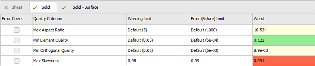
Worst: Displays the metric value for the worst quality element for each metric and provides color coding for the quality metric displayed. The green color indicates that no elements exceed the Warning Limit. Yellow color highlights indicates that bad elements exceed Warning Limit but not Error Limit and red color indicates that the worst element(s) exceed the Error limit. For some metrics, a high value is considered as bad. For example, Skewness. For other metrics, a low value is considered bad. For example, tet collapse. See Mesh Metrics for more details on quality metrics. In the below image, you can see that Min Element Quality is green (good), Max Aspect Ratio and Min Orthogonal Quality are yellow (warning) and Max Skewness is red (Error).
If Error Check was selected for the Max Skewness, after completion the mesh becomes invalid.
You can customise the quality criteria as per your preference under Mesh Quality in File > Options > Meshing. The default quality criteria displayed in the worksheet is based on Physics Preference and differs for Sheet, Solid and Solid - Surface.
When you right-click a Quality Criterion in the Mesh Quality Worksheet, you have the following options:
Create NS Group: Failed Elements: Generates element based named selection groups to view the failed elements in the mesh when you select the named selection group in the tree. Create NS Group: Failed Elements is available in Solid and Sheet tab.
Create NS Group: Warning Elements: Generates element based named selection groups to view the warning elements in the mesh when you select the named selection group in the tree. Create NS Group: Warning Elements is available in Solid and Sheet tab.
Show Contours: Sets the Display style to selected quality criterion when Check Mesh Quality is No, or Yes, Errors and Warnings, or Yes, Errors.
Show Contours sets the Display Style to selected quality criterion and displays the warning (yellow) and failed (red) elements for the selected quality criterion when Check Mesh Quality is set to Mesh Quality Worksheet. Show Contours is available in Sheet, Solid, Solid-Surface tabs.
Show Histogram: Displays the mesh metrics histogram for the selected quality criterion. Show Histogram is available in Solid and Sheet tab.
Isolate Failed Element Bodies: Isolate the failed element bodies for the selected quality criterion. Isolate Failed Element Bodies is available in Solid and Sheet tab.
Open Troubleshooting Documentation: Opens the troubleshooting documentation page from the browser. Open Troubleshooting Documentation is available in all tabs.
If Create NS Group: Failed Elements or Create NS Group: Warning Elements is used, you can right-click the created named selection group in the tree and click Select Mesh Clusters in Group to select all the elements clusters in the named selection. You can then use the Walk under the Selection tab to navigate through the clusters of problem elements.
You can click File > Options > Meshing and select Check Mesh Quality as Mesh Quality Worksheet under Quality in Meshing to use the worksheet as the default for mesh validation method.
You can customize the quality criteria as per your preference under Mesh Quality in File > Options > Meshing. The default quality criteria displayed in the worksheet differs for Sheet, Solid and Solid - Surface.
You can select On or Off to hide or display the quality criteria in the Mesh Quality Worksheet from File > Options > Meshing > Mesh Quality. Mesh Quality Worksheet calculates quality for available criteria only when you mesh or refresh the worksheet. You should hide quality criteria that are not used, to reduce time taken for quality calculation in larger meshes.
When Check Mesh Quality is set to Quality Worksheet and you can view contours of mesh quality using Display Style, the properties of the contours are modified from the default display. For a given criterion, the Geometry window displays elements between the Warning Limit and Error Limit a as yellow and ones exceeding the Error Limit as red.
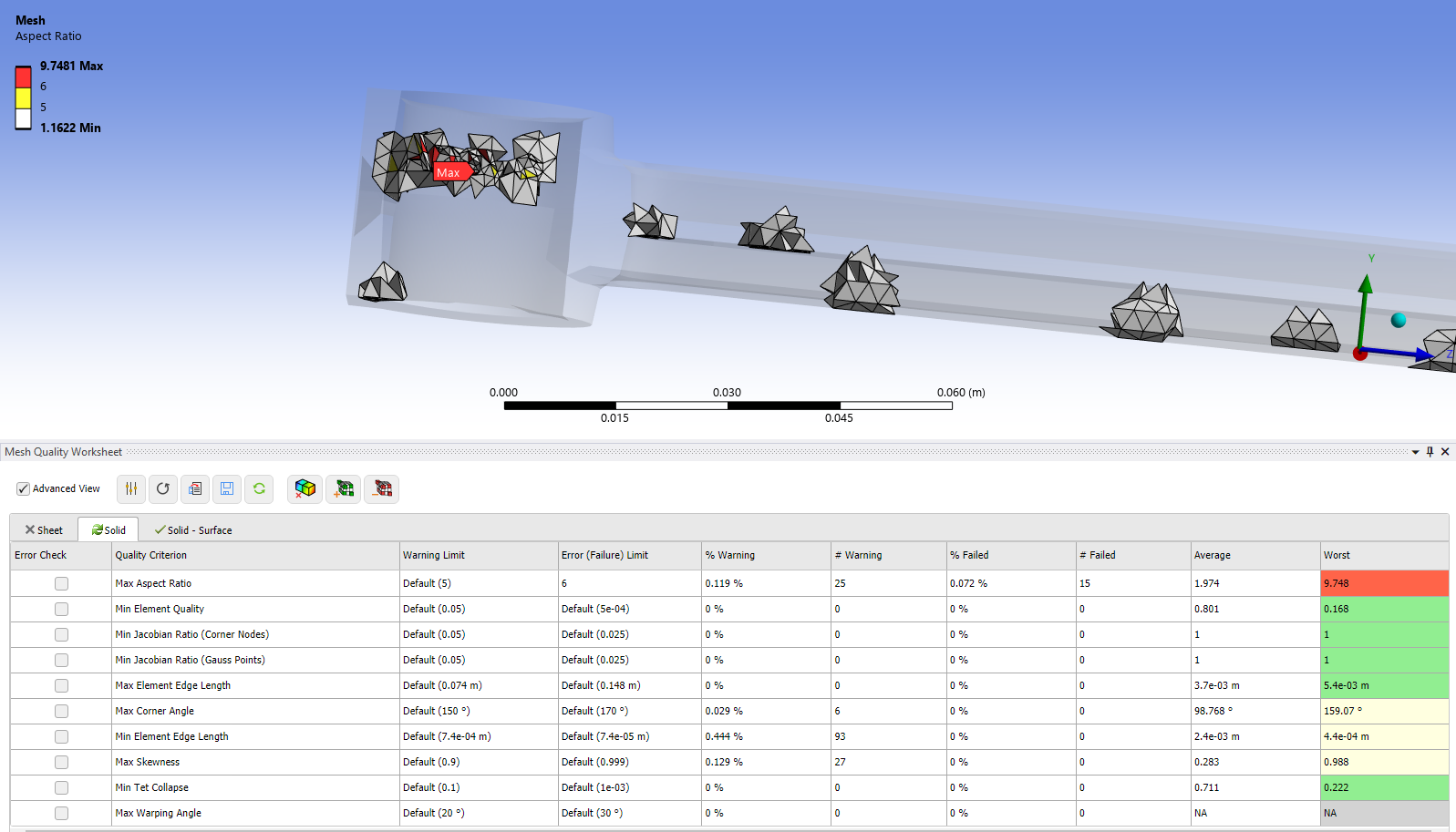
Some additional element layers in grey color around the red color and yellow color
elements help you understand the cause for mesh issues. To increase the number of
mesh layers for required quality elements press Shift+W or
, for
decreasing number of mesh layers for required quality elements press
Shift+S or . If you press
Shift+W or several times, all mesh
elements are shown. To go back to the cluster view, you must use
Shift+S or to remove element
layers.
Limitation
When you enable Error Check for any mesh metrics in the Mesh Quality Worksheet, Mesh Quality Worksheet does not invalidate the mesh generated by the Mesh Workflow.