


When preparing geometry for meshing, it may be advantageous to split a face. This can be achieved by creating Virtual Split Face objects, which allow you to split a face along two vertices to create 1 to N virtual faces. The selected vertices must be located on the face that you want to split.
Splitting a Face
Insert a Virtual Topology object in the tree.
Choose the vertex selection filter and then in the Geometry window, pick two vertices on the face that you want to split.
Note:The vertices must be attached to the same face and in the same part.
Optionally, you can create one or more Virtual Hard Vertex objects to facilitate the split face operation. Virtual Hard Vertex objects allow you to define a hard point according to your cursor location on a face, and then use that hard point in the split face operation. Refer to Creating and Managing Virtual Hard Vertices.
To see all vertices in the Geometry window, including any virtual hard vertices, make sure that the Show Vertices option is enabled.
Create the Virtual Split Face by doing one of the following:
Choose on the Virtual Topology context toolbar.
Click right mouse button on the Virtual Topology object and select from the context menu.
Click right mouse button in the Geometry window and select from the context menu.
Note:If the software cannot create the split, the error message “Unable to split face at selected vertices, please ensure vertices are attached to the same face and in the same part” will appear and the split will not be created.
To change the location of a virtual hard vertex interactively, select it in the Geometry view. Then, while pressing F4 on the keyboard, drag the mouse to move the vertex to the desired location. You cannot move the vertex beyond the face on which it was created. The display indicates the initial 3-D location of the vertex, together with a preview of its new location.
When you change the location of a virtual hard vertex, the corresponding face split is adjusted accordingly.
You cannot use the Virtual Topology Properties dialog to change the location of a virtual hard vertex.
Special Considerations for Virtual Split Faces
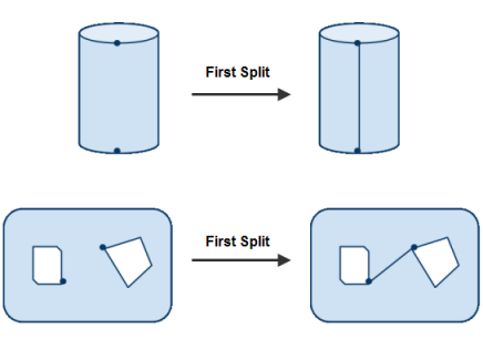
Certain types of faces cannot be split by a single split operation; they require two splits. For example, refer to the cylindrical face in the figure below. As a result of the first split, a seam edge is created and the face is no longer a periodic face. To actually split the cylindrical face, you then must select two more vertices and split the face a second time.
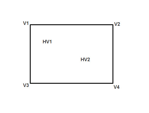
To split a face along more than two vertices you must perform a series of split face operations using two vertices at a time. For example, refer to the figure below, where V1, V2, V3, and V4 are vertices, and HV1 and HV2 are virtual hard vertices. Splitting the face through V1, HV1, HV2, and V4 would require three split operations:
Select V1 and HV1 and split the face.
Select HV1 and HV2 and split the face.
Select HV2 and V4 and split the face.
Virtual Split Face Dependency
Existing virtual faces and/or existing virtual split faces can be used to create new virtual split faces. Within the split face hierarchy, a virtual split face depends on a virtual face if the latter is used to create the former. Similarly, a virtual split face depends on another virtual split face if the latter is used to create the former.
Faces can be split by selecting vertices of virtual split edges, providing the vertices meet the requirements described in the procedure above.
Note: If a virtual face was created from a virtual split face, you cannot delete the virtual split face without first deleting the virtual face. Conversely, if a virtual split face was created from a virtual face, you cannot delete the virtual face without first deleting the virtual split face.
If a virtual split face was created from vertices of virtual split edges, you cannot delete the virtual split edges without first deleting the virtual split face.
If a virtual split face was created from virtual hard vertices, you cannot delete the virtual hard vertices without first deleting the virtual split face.
A warning message appears in the Messages window for each failed deletion. To highlight the geometry that is responsible for a message, select the message, right-click, and select Show Problematic Geometry from the context menu.