


Mesh connections enable you to join the meshes of topologically disconnected surface bodies that may reside in different parts. They are an alternate option to connecting the geometry (for example, by using the DesignModeler application to repair small gaps). However, geometry tolerances are tighter than the tolerances used by mesh connections and often lead to problems in obtaining conformal mesh.
Scoping
With mesh connections, the connections are made at the mesh level and tolerance is based locally on mesh size. Connections are made edge-to-face or vertex-to-face, they connect edge(s) or vertices on face(s) to another face to pinch out the gap and create conformal mesh between the edge(s) and face(s).
Since mesh connections are a post mesh process–the mesh is pinched in a separate step after meshing is complete–the base mesh is stored to allow for quicker updates. That is, if you change a mesh connection or meshing control, only local re-meshing is required to clean up the neighboring mesh.
Note: With Ansys Workbench Release 16.0, post pinch behaviors are migrated into Mesh Connections. When you regenerate a mesh that was created using Pinch Behavior settings, the new mesh might report different results than the previous mesh.
Surface Bodies With No Shared Topology:
Same Surface Bodies With Edge-To-Edge Mesh Connection Established:
Treatment of Legacy Databases
Resuming a legacy database (prior to v16), the application moves Mesh Connection objects and the associated Connection Group folders that contain them to the new Model-level Mesh Edit parent folder.
Application
To apply mesh connections:
Insert Mesh Connection objects automatically or manually.
Mesh connections can be automatically generated using the option available from the right-click context menu of the Mesh Connections or Mesh Connection Group folder. The Tolerance Value, pairing type, and other properties used for auto detection can be set in the Details view of the Mesh Connection Group folder under the Auto Detection category. Sheet thickness can also be used as a Tolerance Value.
The automatic mesh connections feature is very helpful, but it can only detect edge-to-face connections. If you need to define edge-to-edge connections, you will need to define them manually. The feature can also find and create connections that you may not want. Always review the connections, or at least be aware that if problems arise, they may be due to automatically generated mesh connections.
For more control, or to control the engineering design, you may want to insert Mesh Connection objects manually.
Highlight the Mesh Connection Group folder and select the option on the Mesh Edit context tab, or right-click the object and select > .
The option is also available when the top-level Mesh/Mesh Edit folder is selected. Selecting the option at this level adds a Mesh Connection Group object in addition to a Mesh Connection object.
You can also select one or more Contact Regions or the Contacts folder, right-click, and select >. This option enables you to create Mesh Connection objects from Contact Regions. The application scopes the new Mesh Connection objects to the geometries of the Contact Region(s) and sets the tolerance to be equal to the trim tolerance of the contact region. The Mesh connections are added into a new Mesh Connection Group folder.
In the Details view specify Primary Geometry and Secondary Geometry.
"Primary" indicates the topology that will be captured after the operation is complete. That is, it is the topology to which the secondary topologies in the connection are projected.
"Secondary" indicates the topology that will be pinched out during the operation. That is, it is the topology that is projected and merged with the primary.
The primary geometry can be one or more faces or edges. The secondary geometry can only be one or more edges or vertices. When specifying faces, the annotation is displayed on both sides of the faces.
Note: Mesh connections support common imprints, which involve multiple secondaries connected at the same location to a common primary. See Common Imprints and Mesh Connections.
In the Details view specify Tolerance. The Tolerance here has a similar meaning to the Tolerance Value global connection setting, and is represented as a transparent sphere. See Tolerances Used in Mesh Connections for details about Tolerance and how it relates to the Snap Tolerance described below.
For edge-to-face mesh connections only, in the Details view specify Snap to Boundary and Snap Type. When Snap to Boundary is Yes (the default) and the distance from a secondary edge to the closest mesh boundary of the primary face is within the specified snap to boundary tolerance, nodes from the secondary edge are projected onto the boundary of the primary face. The joined edge will be on the primary face along with other edges on the primary face that fall within the defined pinch control tolerance. See Pinch Control for details.
Snap Type appears only when the value of Snap to Boundary is Yes.
If Snap Type is set to Manual Tolerance (the default), a Snap Tolerance field appears where you may enter a numerical value greater than 0. By default, the Snap Tolerance is set equal to the pinch tolerance but it can be overridden here. See Tolerances Used in Mesh Connections for details about Snap Tolerance and how it relates to the Tolerance described above.
If Snap Type is set to Element Size Factor, a Primary Element Size Factor field appears where you may enter a numerical value greater than 0. The value entered should be a factor of the local element size of the primary topology.
Highlight the Mesh Edit folder and choose (right-click and choose from context menu). The surface bodies are displayed and show the mesh connections.
If necessary, review the mesh connections:
Select one or more Mesh Connection or Mesh Connection Group objects, right-click, and select .
A named selection is created for each mesh connection you selected. If you selected a mesh connection group, a named selection is created for each mesh connection within the group. Each named selection is automatically given the same name as the mesh connection from which you created it.
Click a named selection to view the mesh for the mesh connection.
Tolerances Used in Mesh Connections
You can set two separate tolerances to define mesh connections. Setting appropriate tolerances is often critical to obtaining high quality mesh that adequately represents the geometry you want to capture.
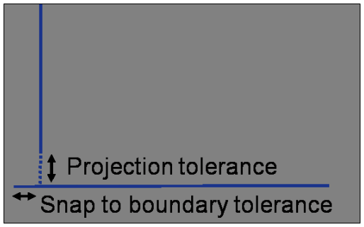
Tolerance – Projection tolerance to close gaps between bodies.
Snap Tolerance – Snap to boundary tolerance to sew up mesh at the connection (applicable to edge-to-face mesh connections only).
The Tolerance value is used to find which bodies should be connected to which other bodies. Setting a larger Tolerance connects more bodies together, while setting it smaller may cause some connections to be missed. For this reason, you might want to set this to a larger value than needed. Setting a smaller value can avoid problems in automatic mesh connection creation, but can also result in other problems because the tolerance used in meshing is inherited from automatic mesh connection detection settings.
Using a Large Tolerance Value
For a large assembly for which you do not want to define mesh connections manually, automatic mesh connection detection provides many benefits. Setting a large Tolerance value to find connections yields more connections, which provides a higher level of comfort that the model is fully constrained. However, larger values can be problematic for the following reasons:
When more automatic mesh connections are created, more duplicates can be created and the mesher decides ultimately which connections to create. In general, making these decisions yourself is a better approach.
The Snap Tolerance defaults to the same value as the Tolerance. If the value of Tolerance is too large for Snap Tolerance, the mesher may be too aggressive in pinching out mesh at the connection, and hence the mesh quality and feature capturing may suffer.
Using a Small Tolerance Value
When mesh connections are generated automatically, the Tolerance is used on the geometry edges and faces to determine which entities should be connected. However, the connections themselves are not generated until meshing occurs. Because the connections are performed on nodes and elements of the mesh rather than on the geometry, the tolerances do not translate exactly.
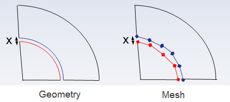
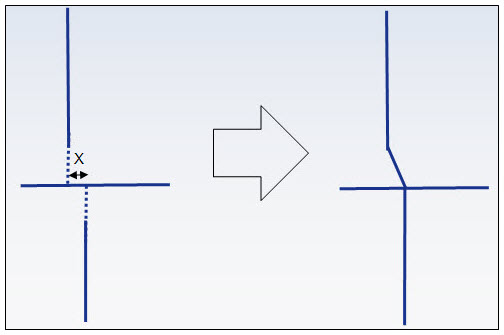
For example, in the case below, you would want to set a Tolerance that is slightly larger than the gap in the geometry. If the gap is defined as x and the tolerance is set to x, automatic mesh connection detection could find the connection, but the meshing process may result in mesh that is only partially connected.
Tips for Setting Tolerances
As detailed above, setting the correct tolerance can be very important, and in some cases may require some speculation and/or experimentation. The following tips may help:
You can adjust the Tolerance used to generate automatic mesh connections after the connections are found. Sometimes it is a good idea to use one Tolerance value to find the mesh connections, select all the mesh connections, and then reduce or increase the Tolerance later.
Having Snap to Boundary turned on and using a Snap Tolerance are not always advisable. It depends on the model and the features you want to capture.
Mesh Sizing and Mesh Connections
Mesh size has an effect on the quality and feature capture of a mesh connection as follows:
Mesh size always affects the base mesh, as features are only captured relative to mesh size.
During mesh connection processing, the base mesh is adjusted according to the common imprint/location. In cases where there is a large projection or a large difference in mesh sizes between the primary entity and the secondary entity, the common edge between bodies can become jagged. Also, as local smoothing takes place, there can be some problems in transition of element sizes. You can often use one of the following strategies to fix the problem:
Use more similar sizes between source and target.
Improve the tolerance used by mesh connections (either for projection, or for snapping to boundary).
Adjust the geometry's topology so that the base mesh is more accommodating to the mesh connection.
See Common Imprints and Mesh Connections.
Common Imprints and Mesh Connections
The tolerance for common imprints comes from the minimum element size in the footprint mesh, which is the horizontal plate in the example below. Common imprints are made if the gap between imprints is smaller than or equal to 5 percent of the element size in the connection region. For this reason, setting the mesh size appropriately is important to control whether the imprints will be common or not.
For example, in the case shown below, if you want a common imprint, the minimum element size is set to Yes) should be >x.
In this case, you could scope local face mesh sizing on the horizontal plate to control the sizing.
Mesh Connections for Selected Bodies
You can select a geometric entity and lookup the mesh connection object in the tree outline. To find the relevant mesh connection object:
Right-click a geometric entity, and then click > .
Mesh Connections Common to Selected Bodies
You can select a pair of geometric entities and lookup the shared Mesh Connection object in the tree outline. To find a relevant mesh connection object:
Select the appropriate pair, and then click Go To > .
This option can be helpful for finding spurious mesh connections, in which case duplicates can be removed.
Displaying Multiple Views of Mesh Connections
Use the Body Views button on the Mesh Edit Context tab to display parts in separate auxiliary windows.
For closer inspection of mesh connections, you can use the Show Mesh option on the Display Context tab along with Body Views and the Sync Views toggle button. When the Body Views button is engaged, any manipulation of the model in the Geometry window will also be reflected in both auxiliary windows. The Body Views toggle button enables you to display parts in separate windows and the Sync Views toggle button, when activated, causes any change in the Geometry window to also be reflected in the auxiliary windows.
Merging Mesh Connections
Mesh connections can be merged by selecting the desired objects, right-clicking, and selecting the Merge Selected Mesh Connections option. During the process, the application deletes the original objects and creates a new Mesh Connection object with a combined scoping.
Mesh Connections can only be merged under the following criteria:
The mesh connections are not already connected.
The primary and secondary geometry must have similar topology for the connections being merged. For example, if you are merging two connections and the first has a face for the primary geometry and the second has an edge for the primary geometry, the connections cannot be merged. If both primaries are faces and both secondaries are edges, the connections can be merged.
When mesh connections are merged, the new mesh connections contain the merged set of entities as primaries and secondaries.
Note: Be aware that the merge operation process can create undesired connections. This can create a connection that is not appropriate for mesh generation.
Diagnosing Failed Mesh Connections
The state of each mesh connection is displayed in the Tree Outline. For a description of the various states, see Understanding Mesh Connection and Contact Match States.
General Failures
In the event of a general mesh connection failure, the following approach is recommended:
Select an ignored or failed mesh connection shown in the tree and look at Control Messages in the Details View.
Note: You can use the Filter to identify Mesh Connection objects that are State>Ignored. However, if a mesh connection is in an “error” state, it cannot be filtered in the tree.
Click Yes, Click to Display to display related error messages.
Right-click the error messages:
If a message provides “Problematic Geometry” information:
Select the message, right-click, and select from the context menu.
This action highlights the geometry in the Geometry window that is responsible for the message.
Note: Any error message that is related to a specific mesh connection will be associated with the secondary geometry in the connection.
Select the problematic bodies, right-click, and select Go To > Mesh Connections for Selected Bodies.
This action highlights all mesh connections attached to the problematic geometry.
Review the tolerances and mesh sizes associated with the highlighted connections.
If a message provides “Go to Body” information:
Select the message, right-click, and select from the context menu.
This action highlights the object in the Details view that is responsible for the message.
Review the tolerances and mesh sizes associated with the highlighted body or bodies.
This action highlights all mesh connections attached to the problematic geometry.
- Mesh Connection Failure
If you receive an error or warning message about one or more mesh connections:
Highlight and review the message.
Right-click the message and select the option . The corresponding Mesh Connection object that is at issue becomes active in the tree.
Verify that all of the associated properties are properly defined.
Right-click the message and select the option . The corresponding Primary/Secondary geometry that is at issue becomes highlighted in the Graphics window.
Verify that the all of the associated geometries are properly defined.
Failures Due to Defeaturing from MultiZone Quad/Tri Meshing and/or Pinch Controls
Due to the patch independent nature of the MultiZone Quad/Tri mesh method, a connection may fail because the mesh is associated with some face of the body but not with the face that is involved in the connection. This type of mesh connection failure, which may also occur when pinch controls are defined, is the result of the part mesh being significantly defeatured prior to mesh connection generation. To avoid mesh connection failures when using MultiZone Quad/Tri and/or pinch controls, use one of the following approaches:
Use virtual topology to merge the faces of interest with the adjacent faces to create large patches, and then apply mesh connections to the patches.
Protect small faces in mesh connections by defining Named Selections.
The software does not automatically extend the connection region because doing so may lose the engineering intent of the model.
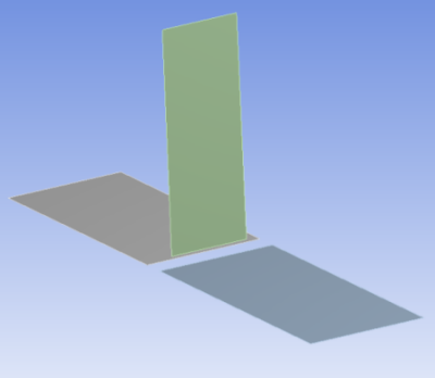
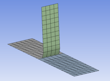
For example, consider the two parts shown below.
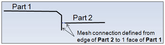
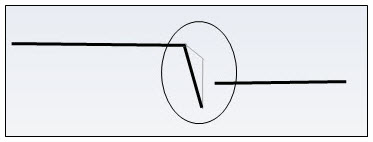
If you are using the MultiZone Quad/Tri mesh method or pinch controls, the part mesh may look like the one shown below. Notice that one face has been defeatured out.
In this case:
If the defeatured face is the one defined in the mesh connection, the connection will fail.
If the other face is the one defined in the mesh connection, the connection will succeed.
If you include both faces in the mesh connection, the connection will succeed.
Since you cannot always control which face is defeatured, the most robust and recommended approach is to include both faces in the mesh connection.
Points to Remember
After model assembly, you cannot generate new mesh connections in a mesh that already has mesh connections. Mesh connections only work with a model assembly if the mesh is unconnected in the upstream systems. Because the base meshes from the upstream systems are not available to the assembled model, you must regenerate the mesh to use mesh connections.
The mesh must be up-to-date before you can generate mesh connections.
If the mesh is not up-to-date, then the base mesh will be regenerated when you generate the mesh connections.
Although the tolerance used for finding mesh connections and for generating mesh connections may be the same value, the tolerance itself has slightly different meanings in the two operations. When finding mesh connections, the tolerance is used to identify pairs of geometry edges or face(s)/edge(s). When generating mesh connections, the tolerance is used in pinching together the edge mesh or edge/face mesh. Since the geometry consists of NURBS, and the mesh consists of linear edges, the same tolerance may mean something slightly different in the two operations.
For example, consider a geometry that consists of two cylindrical sheet parts that share an interface constructed from the same circle. Also consider that you are finding mesh connections with a tolerance of 0.0. In this case, the mesh connection is easily found because the two edges are exactly the same. However, when the mesh connection is being formed, some segments of the edge may fail to be pinched together if the mesh spacing of the two parts is different and therefore the tolerance of the edge mesh is different. Also see Tolerances Used in Mesh Connections.
For a higher order element, a midside node along the connection between a secondary and a primary is located at the midpoint between its end nodes, instead of being projected onto the geometry.
Although mesh connections do not alter the geometry, their effects can be previewed and toggled using the Display Context tab.
For Error Limits, mesh connections support the Standard Mechanical option only.
If you define a mesh connection on topology to which a match control, Face Meshing control, or inflation control (global or local) is already applied, the mesh connection may alter the mesh, which in turn may eliminate or disable the match, mapped face meshing, or inflation control.
Mesh connections cannot be mixed with refinement or post inflation controls.
A mesh connection scoped to geometries (for the primary and the secondary) that lie on the same face are ignored by the mesher, and, as a result, no mesh connection is generated.
Refer to Clearing Generated Data for information about using the Clear Generated Data option on parts and bodies that have been joined by mesh connections.
Refer to Using the Mesh Worksheet to Create a Selective Meshing History for information about how mesh connection operations are processed by the Mesh worksheet.
Mesh connections are not supported for external mesh models.
Mesh connections are not supported between solid bodies and sheet bodies in a multibody part, or between sheet bodies and line bodies in a multibody part.