Notes on Virtual Cell Creation
Scoped objects except other virtual cells may need to be relinked to the new virtual cells when that virtual cell is composed of entities in the scoped object. When the virtual cell is deleted the object may need to be rescoped to the original entities.
All scoped objects except for mesh controls and other virtual cells will be protected during automatic virtual cell generation. This will allow users to load their models and run auto virtual topology without deleting loads. All faces within a protected object may be merged with faces in the same protected object and not in any other protected object.
If Generate on Update is set to Yes and you update the geometry, all Virtual Cell objects that were created automatically will be deleted and recreated based on the new geometry. Any loads that were attached to geometry within the deleted Virtual Cell objects will need to be reattached to the new geometry.
If Generate on Update is set to No and you update the geometry, all Virtual Cell objects that were created automatically should remain persistent barring major topology changes of the model being updated. Reapplication of loads may not be necessary.
For any virtual cells that were generated, you can choose whether the nodes will be projected back to the underlying geometry (in contrast to the virtual cell’s faceted geometry). To do so, select the desired virtual cell and use the Virtual Topology Properties dialog to set the Project to Underlying Geometry option to Yes or No. The default is Yes for analytical geometry. Otherwise, the default is No. Computational expense increases when the option is set to Yes. Use these guidelines:
Yes is recommended if:
You are using virtual topology to fine tune the topology of your mesh and need precise control from the Size Function.
Your geometry is valid and you want the mesh to capture it accurately. Here, there may be a slight impact on performance.
No is recommended if:
You are using virtual topology to simplify bad/corrupt geometry or topology.
You are trying to grossly defeature a model (for example, remove bosses, serial numbers and so on).
Virtual Cell Logic and Usage
The Virtual Topology feature is a cell dependency operation where existing virtual cells can be used to create new virtual cells both manually and automatically. Within the cell hierarchy, a virtual cell depends on another virtual cell if the latter is used to create the former.
Virtual Face Dependency
A virtual face depends on a virtual edge if during the face creation the virtual edge is used to create virtual face loops. A virtual face depends on another virtual face if the latter was used to create the former.
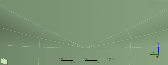
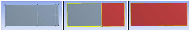
The following image represents the Merge Face Edges in the off position.
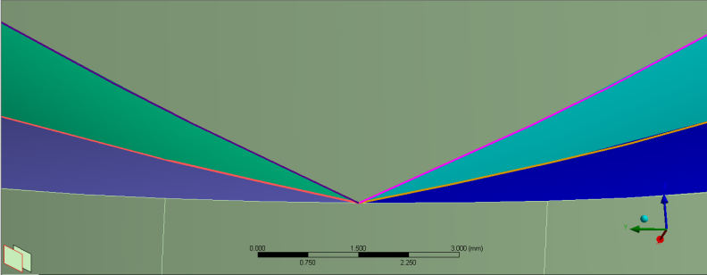
The following image represents the Merge Face Edges in the on position.
Virtual Edge Dependency
A virtual edge depends on a virtual face if during the edge creation an owner loop belongs to the said face. A virtual edge depends on another virtual edge if the latter was used to create the former.
Note:
If a virtual edge was created from a virtual split edge, you cannot delete the virtual split edge without first deleting the virtual edge. Conversely, if a virtual split edge was created from a virtual edge, you cannot delete the virtual edge without first deleting the virtual split edge.
A warning message appears in the Messages window for each failed deletion. To highlight the geometry that is responsible for a message, select the message, right-click, and select Show Problematic Geometry from the context menu.
In addition, if the virtual edge belongs to a virtual face, the virtual face will not be deleted either.
A warning message appears in the Messages window for the virtual face, and you can use the Show Problematic Geometry option to highlight the face.
You can manually designate faces and edges for inclusion into a virtual cell, or you can have the Mechanical application or the Meshing application automatically create virtual cells based on settings that you specify. You can use the Automatic mode to globally reduce the number of faces and edges where possible, or use Repair to focus more closely on problematic faces and edges. The geometry under a virtual cell is represented by the underlying cell's graphic resolution.
Note:
There are geometric limitations to creating virtual cells, including those related to cells that would have too much curvature, or other limitations in trying to represent a group of cells by a single cell.
The tessellation of models from CATIA4 may not be appropriate for virtual topology, which could prevent the creation of virtual cells for these models.
Creating Virtual Cells Manually
Insert a Virtual Topology object in the tree.
Choose the face (Ctrl+F) or edge (Ctrl+E) selection filter, and then pick one or more faces or one or more edges that you want to include in the virtual cell(s).
You can use the button to identify tightly clustered vertices that might need to be merged.
Create the Virtual Cell object(s) by doing one of the following:
Choose on the Virtual Topology context toolbar. You can also use Ctrl+M to merge either the faces after selecting them, or the common edge between faces.
Click the right mouse button on the Virtual Topology object and select from the context menu.
Click the right mouse button in the Geometry window and select from the context menu.
From the selected set of faces or edges, the software creates the virtual cell(s). During this process, adjacent selected entities are grouped appropriately to form virtual cell(s), while any single selected entity (that is, one that is selected but is not adjacent to any other selected entity) forms its own virtual cell. An error message appears in the Messages window for each subset of failed topologies. To highlight the geometry that is responsible for a message, select the message, right-click, and select Show Problematic Geometry from the context menu. Refer to the examples below.
Note:
A virtual cell cannot be created on a single edge that is straight or enclosed with no vertices.
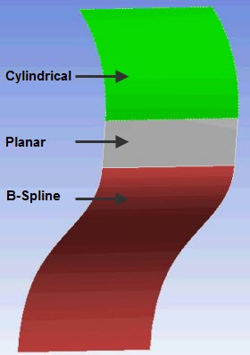
A virtual cell cannot be created on a single face that is cylindrical or planar. For example, if you select either the top face or middle face in the figure below and try to create a virtual cell, no virtual cell will be created. However, selecting the bottom face will result in creation of a virtual cell.
Examples of Virtual Cell Formation
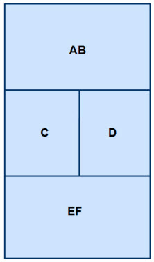
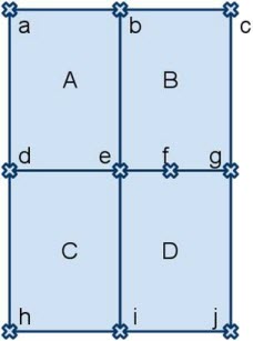
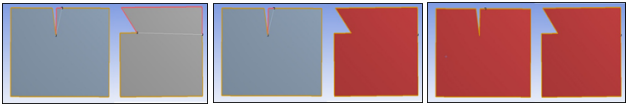
In the example shown in Figure 205: Formation of Virtual Faces, suppose that you select faces A, B, E, and F and then select . As a result, virtual faces AB and EF will be formed, as shown in Figure 206: Virtual Faces After Operation.
The edges would be handled according to the Merge Face Edges setting. For example, if Merge Face Edges is set to Yes, virtual edges ac and km also will be formed.
As another example, using the same starting point, if you select faces A, E, and F and then select , virtual faces A and EF will be formed. In this case, if Merge Face Edges is set to Yes, virtual edge km also will be formed.

In the example shown in Figure 207: Formation of Virtual Edges, suppose that you select all edges and then select . In this case, only virtual edge eg will be formed because only those virtual edges that can be formed without forcing face merges will be created.
Creating Virtual Cells Automatically Using Automatic Mode
Insert a Virtual Topology object in the tree.
In the Details View, ensure that Method is set to Automatic.
Make adjustments as needed to any of the following settings in the Details View:
Behavior – Determines how aggressively the face(s) and edge(s) are merged. The choices are , , , , and . The setting will merge only edges. The setting exposes properties ( and ) and properties (, , , and ). These properties enable you to set parameters that control the creation of automatic Virtual Topologies.
Note: Setting any of the Custom or Advanced Custom Properties to -1 resets the value of that property back to its default.
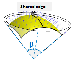
Gauss Curvature Angle – Represents the flatness of the resultant face. If Angle
 is greater than the Gauss Curvature
Angle, the faces will stay separate. Increasing the Curvature Angle
causes a greater number of faces to be grouped into fewer, larger
faces, which might mean that there are fewer resulting Virtual Topologies.
is greater than the Gauss Curvature
Angle, the faces will stay separate. Increasing the Curvature Angle
causes a greater number of faces to be grouped into fewer, larger
faces, which might mean that there are fewer resulting Virtual Topologies. The Gauss Curvature Angle can range from 0-180 degrees. The default setting is 60 degrees. The following figure shows the results of setting the Gauss Curvature Angle to 25, 60, and 120 degrees respectively.
Note: For best results, set the angle between 20 and 120 degrees. If the angle is set below this range, few faces will be merged. Setting the value above this range could result in problems with the mesh. Setting the value above this range could also result in large clusters of faces that ultimately fail to merge into a virtual face.
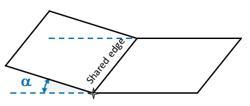
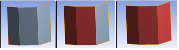
Feature Angle – Sets the minimum angle between faces at a common edge. If Angle
 , as shown in the following figure,
is greater than the Feature Angle, the faces
will stay separate. Faces are merged as the Feature Angle increases.
, as shown in the following figure,
is greater than the Feature Angle, the faces
will stay separate. Faces are merged as the Feature Angle increases. The Feature Angle can range from 0 to 180 degrees. The default setting is 40 degrees. The following figure shows the results of setting the Feature Angle to 20, 40, and 80 degrees respectively.
Note: For best results, set the angle between 30 and 90 degrees. If the angle is set below this range, few faces will be merged. If the value is set above this range, it could result in large clusters of faces that ultimately fail to merge into a virtual face.
Aspect Ratio – The ratio between the area of the face group to the square of the shared boundary length between the face and the Face Group. This setting controls how faces are grouped. Here, increasing the Aspect Ratio causes a greater number of faces to be grouped into fewer, larger faces. The Aspect Ratio can range from 0 to 1. The default setting is 1. The following figure shows the results of setting the Aspect Ratio to 0.2, 0.5, and 0.9, respectively.
Contact Angle – The angle introduced at common vertices between faces. This setting prevents complicated boundaries when grouping faces (for example, angles introduced at contact points between faces). Increasing the Contact Angle causes a greater number of faces to be grouped into fewer, larger faces. The angle can range from 0 to 360 degrees. The default setting is 360 degrees. The following figure shows the results of setting the Contact Angle to 270 degrees, 330 degrees, and 355 degrees, respectively.
Edge Angle – The feature angle between edges at their common vertex. Increasing the Edge Angle causes a greater number of edges to be grouped together. The angle can range from 0 to 180 degrees. The default setting for the Edge Angle is 80 degrees. The following figure shows the results of setting the Edge Angle to 80 degrees, 100 degrees, and 150 degrees, respectively.
Shared Boundary Ratio – The ratio of the length of the common boundary to the length of the smallest perimeter. Increasing the Shared Boundary Ratio causes the number of grouped faces decreases. The ratio can range from 0 to 0.5. The default setting for the ratio is 0. The following figure shows the results of setting the Shared Boundary Ratio to 0.2, 0.3, and 0.4, respectively.
Make adjustments to the Advanced settings in the Details view.
Do one of the following:
Click right mouse button on the Virtual Topology object and choose from the context menu. Virtual cells are automatically created for each region that meets the criteria established by the settings in step 2.
These virtual cells remain valid after a geometry update.
Choose the face (Ctrl+F) or body selection filter and pick two or more faces or two or more bodies. Click right mouse button on the Virtual Topology object and choose from the context menu. From the selected set of faces or bodies, the software groups adjacent entities appropriately and automatically creates virtual cells for each region that meets the criteria established by the settings in step 3.
These virtual cells become invalid after a geometry update.

Creating Virtual Cells Automatically Using Repair Mode
Insert a Virtual Topology object in the tree.
In the Details View change the Method to Repair.
Make adjustments as needed to any of the following settings in the Details View:
Behavior – Determines the type of repair to be performed. The choices are Repair All, Repair Small Edges, Repair Slivers, and Repair Small Faces.
The Repair Small Edges setting tries to remove all the small edges, satisfying the Repair Settings criteria displayed in the Details View. The small edges are removed either by merging their attached faces or by merging the small edge with an adjacent edge. The Repair Small Edges setting exposes the Max Edge Length and Min Edge Length settings. The edges with lengths between Max Edge Length and Min Edge Length are repaired.
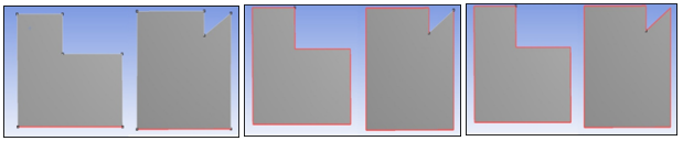
The following example, the first figure shows small edges between faces.
After Small Edge Repair (as shown in the following figure) with Max Edge Length set to 0.5 mm and Min Edge Length set to 0 mm, the small edges are removed by the faces being merged.
In the following figure, small edges are attached to the same faces.
After Small Edge Repair with Max Edge Length set to 0.9 mm and Min Edge Length set to 0 mm, the small edges are merged.
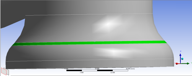
The Repair Slivers option tries to remove all the slivers, satisfying the Repair Settings criteria shown in the Details View. The slivers are removed by merging the sliver face with another adjacent face. The Repair Slivers option exposes the Max Sliver Width and Min Sliver Width options. The sliver faces with width between Max Sliver Width and Min Sliver Width are repaired.
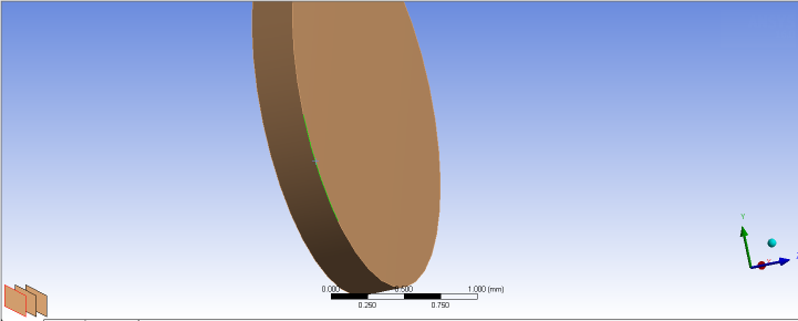
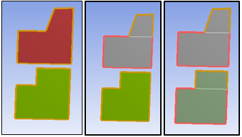
The following figure shows a geometry with a sliver face.
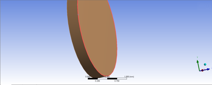
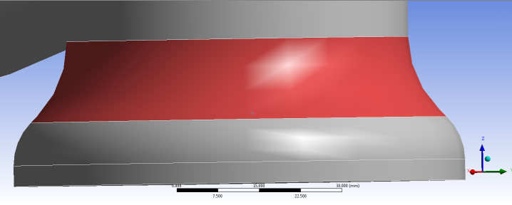
After Sliver Repair with Max Sliver Length set to 2 mm and Min Sliver Length to 0 mm, the sliver face is merged with an adjacent face.
The Repair Small Faces option tries to remove all the small faces satisfying the Repair Settings criteria shown in the Details View. The small faces are removed by merging the small face with another adjacent face.
The Repair Small Faces option exposes the Max Face Area and Min Face Area options. The faces with area between Max Face Area and Min Face Area are repaired.
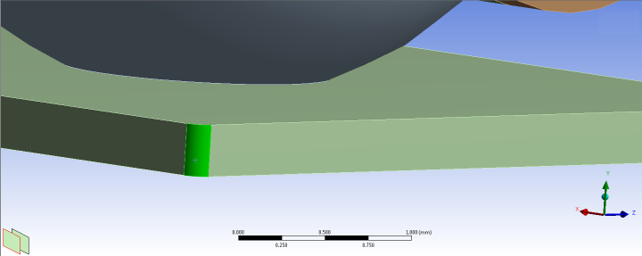
The following figure shows a small face.
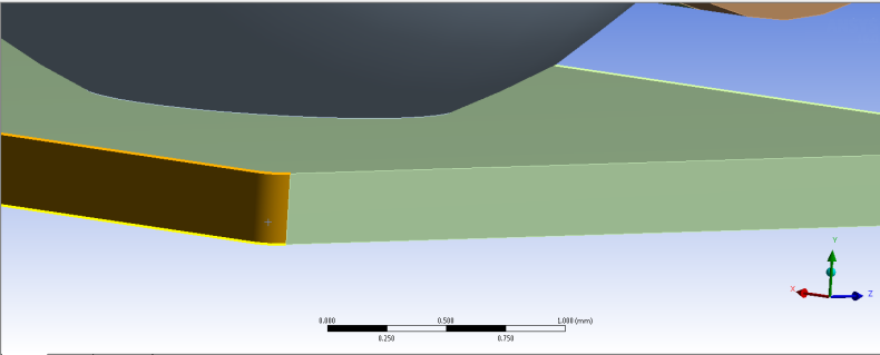
After small face repair with Max Face Area set to 0.04 mm2 and Min Face Area set to 0 mm2, the small face is merged with an adjacent face.
The Repair All setting tries to remove all of the small edges, sliver faces, and small faces that satisfy the Repair Settings criteria shown in the Details View.
Repair Settings– Exposes settings like Max Edge Length and Min Edge Length, depending on the Behavior settings. The default values for different Repair Settings are:
Max Edge Length: Default is set to ½ Min Size (available under Sizing in mesh when Size Function is turned ON)
Min Edge Length: Default is 0, or no lower limit
Max Face Area: Default is set to (½ Min Size)2.
Min Face Area: Default is 0, or no lower limit
Max Sliver Width: Default is set to ½ Min Size
Min Sliver Width: Default is 0, or no lower limit
Note: Setting any of the Repair Settings to -1 resets the value of that setting back to its default.
Make adjustments to the Advanced settings in the Details view.
Do one of the following:
Click right mouse button on the Virtual Topology object and choose from the context menu. Virtual cells are automatically created for each region that meets the criteria established by the settings in step 2.
These virtual cells remain valid after a geometry update.
Choose the face (Ctrl+F) or body selection filter and pick two or more faces or two or more bodies. Click right mouse button on the Virtual Topology object and choose from the context menu. From the selected set of faces or bodies, the software groups adjacent entities appropriately and automatically creates virtual cells for each region that meets the criteria established by the settings in step 3.
These virtual cells become invalid after a geometry update.