Similar to the behavior of the general sweeper, the thin model sweeper creates a structured hexahedral/wedge mesh, but for a thin model. It meshes one side of the thin solid (the source), and then sweeps the mesh to the other side (the target). Unlike the general sweeper, the thin model sweeper does not require a topological one-to-one match of source to target. The model may have multiple source and/or target surfaces. (Refer to Topological Requirements of the Thin Model Sweeper for examples.) In addition, the thin model sweeper can perform some edge defeaturing and allowing it to mesh models that have reasonably small features.
Requirements and usage information specific to the thin model sweeper include the following:
The model must be thin—if the model is too thick, the thin model sweeper algorithm may fail.
The source(s) and target(s) cannot touch each other.
The model must have an obvious "side" that is perpendicular to the source and target, all of the side areas must connect directly from source to target.
Mesh controls defined on the target may not be respected.
Multibody parts are supported.
For multibody parts, only one division through the thickness is possible. For single body parts, you can define multiple elements through the thickness using the Sweep Num Divs control in the Details View of the Sweep Method. (See steps below.)
The thin model sweeper ignores the Proximity Gap Factor setting, which is used to help define the proximity-based sizing. Using the proximity-based sizing in combination with the thin model sweeper may lead to an unnecessarily long computation time.
If two bodies intersect to make a "T" connection, the thin model sweeper does not require that a mapped mesh control be defined at the junction of the two bodies.
The and features do not support the thin model sweeper.
See Notes on Face Meshing Controls for Mapped Meshing for information about using mapped Face Meshing controls with the thin model sweeper.
Considerations for Selecting Source Faces for the Thin Model Sweeper
The thin model sweeper meshes one side of a thin solid (the source), and then sweeps the mesh to the other side (the target). You can control which side the mesher uses as the source by selecting source faces manually. (To do so, set the Src/Trg Selection control to as described below.)
For most geometries, you can select just 1 of the faces in the complete set of faces that you want to be used as the source set, and the mesher will properly identify the other faces that are a part of that source set. However, for more complicated models (such as those containing multibody parts), you need to select all source faces in the source set in order for the mesher to be successful in finding the complete set of source faces.
A general rule of thumb is if you can select a single face and then extend the selection to its limits, the mesher can also identify the proper complete set of source faces. (For details about extending selections, refer to the description of the Extend Selection command in the Mechanical help.) If the geometry contains sharp angles that make the limit extension selection difficult, it will also be difficult for the mesher to use a single face for the source face definition, and you should select the complete set of source faces.
Topological Requirements of the Thin Model Sweeper
If a thin model mesh fails, turn on the Edge Coloring > By Connection option to see if the edge connectivity is unusual. In some cases, the geometry connectivity may not be as expected, and this may create problems during meshing. These problems can be fixed in the DesignModeler application, the CAD package, or possibly through the use of virtual topologies
The thin model sweeper supports M source faces to N target faces, where M and N can be any positive whole numbers. Between source faces and target faces, there must be "side faces." The angles between side faces and either source faces or target faces must be sharp enough that the faces are NOT considered to be smoothly connected. Therefore, a knife with a thin blade would not be appropriate for thin model sweeping because the cutting edge (blade) does not form a "side face." During the thin model sweeping meshing process, the features (vertices, edges, and faces) on the target may not be preserved and therefore, you should avoid applying boundary conditions to the target. The side faces must connect to both source and target. No edges or vertices are allowed on side faces. In this sense, no hard edges on side faces are allowed. Side edges must connect directly from source to target. You can use virtual topology to eliminate some features.
Use Virtual Topology to create a single edge between source and target faces.
Mesh Controls and the Thin Model Sweeper
Mesh Controls applied on the target faces/edges are ignored. Only mesh controls applied to the source faces/edges are respected.
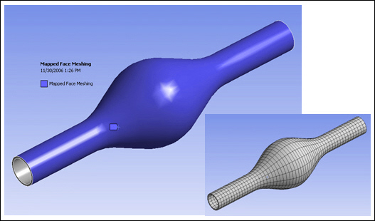
In example (a) below, the Mapped Face Control is ignored because it is applied to the target face.
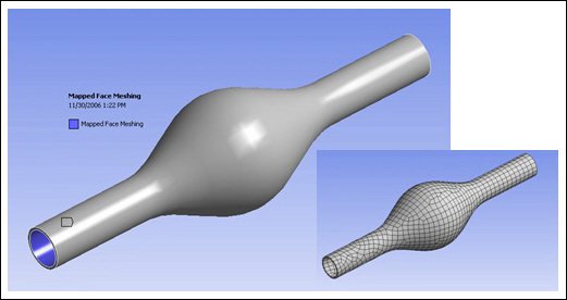
In example (b) below, the Mapped Face Control is respected because it is applied to the source face.
Thin Model Sweeping for Single Body Parts
This section provides the basic steps for using thin model sweeping to mesh a single body part.
To use the Thin Model Sweeper to mesh a single body part:
Click the Mesh object in the Tree and select from the context menu.
Scope the Method control to the thin body.
In Details> Definition, set Method to Sweep.
Set Src/Trg Selection to Manual Thin or Automatic Thin.
Although Automatic Thin may work for simple cases, you may need to select Manual Thin depending on the complexity of the model.
If you selected Manual Thin, scope the source face(s), remembering the recommendations provided in Considerations for Selecting Source Faces for the Thin Model Sweeper.
Enter additional sweep option settings, as desired, in the Details View. These may include Free Face Mesh Type, Sweep Num Divs, and Element Option. For descriptions of these options, see Sweep Method Control.
Define other mesh controls, as desired.
Generate the mesh.
Figure 135: Thin Solid Sweeper Used to Mesh a Single Body Part shows a model of a timing cover that consists of a single body. The thin solid sweeper was used to mesh the body. To obtain this mesh, Free Face Mesh Type was set to , Sweep Num Divs was set to , and Element Option was set to .
Figure 136: Thin Solid Sweeper Used to Mesh a Single Body Part: Detail shows detail of the timing cover. The Sweep Num Divs setting of is apparent in this view.
Thin Model Sweeping for Multibody Parts
This section provides the basic steps for using thin model sweeping to mesh multibody parts. You can define thin sweep for each thin body in the multibody part.
To use the Thin Model Sweeper to mesh a multibody part:
Select a thin body in the Geometry window, right-click, and select Insert> Method.
Set Method to Sweep.
Set Src/Trg Selection to Manual Thin or Automatic Thin.
Although Automatic Thin may work for simple cases, you may need to select Manual Thin depending on the complexity of the model.
If you selected Manual Thin, scope the source face(s) of the thin body, remembering the recommendations provided in Considerations for Selecting Source Faces for the Thin Model Sweeper.
Enter additional sweep option settings for the thin body, as desired, in the Details View. These may include Free Face Mesh Type and Element Option. For descriptions of these options, see Sweep Method Control.
If the part contains multiple thin bodies, repeat step 1 through step 5 for each.
If the part contains any thick sweepable bodies, repeat step 1 through step 5 for each, but set Src/Trg Selection to Automatic, Manual Source, or Manual Source and Target (depending on complexity of the model).
If the part contains any non-sweepable bodies, define mesh methods for each, if desired. If the mesh methods are left undefined, the Meshing application will determine the most appropriate methods to use for the non-sweepable bodies.
Define other mesh controls, as desired.
Generate the mesh.
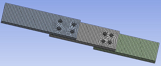
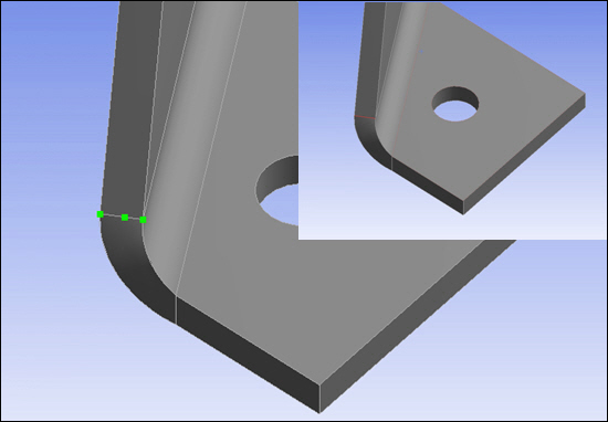
Figure 137: Thin Solid Sweeper Used to Mesh a Multibody Part shows a model of a bracket that consists of four bodies. The thin solid sweeper was used to mesh the bodies. To obtain this mesh, Free Face Mesh Type was set to and Element Option was set to .
Additional Considerations for Using the Thin Model Sweeper
This section describes several models and scenarios to consider before using the thin model sweeper.
The first example involves a multibody part that models a laminated composite material, as shown below. Defining source faces for such models may be confusing.
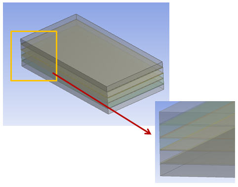
The part contains nine bodies. Assume that the Manual Thin option for Src/Trg Selection will be applied to each of them. With the Manual Thin option, source faces must be defined for each selected body (each body must have at least one face selected as its source face). There are different ways that you can select faces to meet this requirement, and it is logical to assume that defining nine source faces (one for each body) is one way that will work. However, in cases of laminated composites, you must specify every other face as a source face.
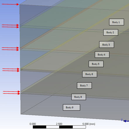
Consider the figure below, in which nine faces (indicated by arrows) are defined as source faces for the nine bodies. As illustrated by the figure, Body 1 has two faces defined as source faces, and the same is true for bodies 2 through 8. This source face definition causes ambiguity for the thin sweep mesher, which will have trouble determining a target face in bodies 1 through 8 and may fail.
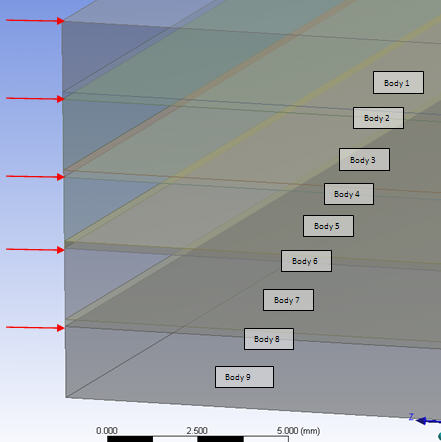
Now look at the figure below. Here every other face has been selected as a source face, for a total of five. With this source face definition, each body still has one face selected to be its source face, so the requirement for Manual Thin source face selection has been met. With this source face definition, the thin sweep mesher will have no problem determining target faces for each of the bodies.
Note: For cases in which the Automatic Thin option can be used, an alternative method to consider is to apply the Manual Thin option to only one body, define its source face, and apply the Automatic Thin option to the remaining bodies.
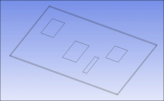
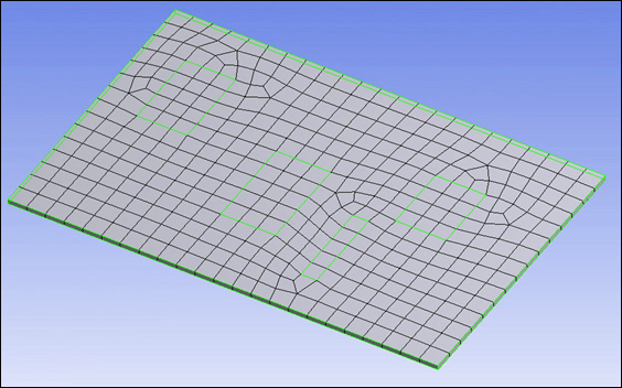
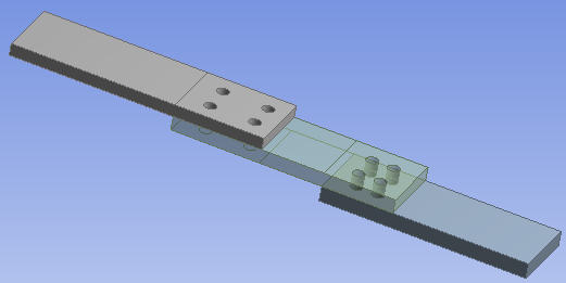
Before using thin solid sweeping, remember that the mesher meshes one side of faces and then sweeps the mesh to the second side of faces. Consider Figure 141: Thin Solid Sweeper Limitation, which shows a model containing three plates. In the thin sweep operation, the edges that are common to two source faces are present on the source side. If the edges are different on the opposite side, the mesher will use the nodes from the source side in the mesh on the opposite side anyway. Thus, if there are features on the non-source side that are unique and need to be captured, you should not use the thin solid sweeping approach, as the mesher will ignore these features.
In Figure 141: Thin Solid Sweeper Limitation, there is no valid way to mesh the middle plate with the thin solid sweep method, as there is an imprint coming from both the plate above and the plate below the middle plate, unless:
The plate is decomposed (sliced) to ensure all target face(s) have a corresponding source face.
The multibody part is broken into single parts (non-conformal mesh at common interfaces).
Some other mesh method is used. (In Figure 141: Thin Solid Sweeper Limitation, a tet mesh method is used.)
The source and target faces have similar pairs, and the source faces are selected properly (described below).
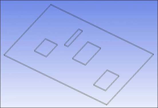
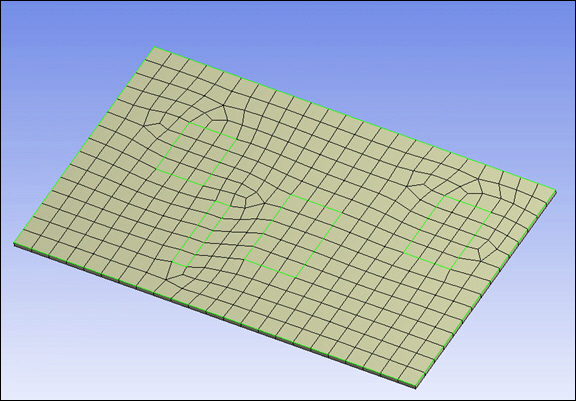
Figure 142: Adding Face Projections (Splits) in the DesignModeler Application illustrates an alternative approach to meshing the model above. In the DesignModeler application, the Projection feature allows face(s) to be split so that the source and target pairs will align. (For this model, the Edges on Face type of projection was used.)
With the addition of the face splits, the model can be meshed successfully with the thin solid sweep method by applying the Manual Thin option for Src/Trg Selection to all three bodies, and defining the top surface of each body as its source faces, as shown below. In this example, two faces are selected as source faces for the body on the left, three for the middle body, and two for the body on the right. Defining the source faces in this way ensures that everything is meshed from one side of the multibody part to the other.
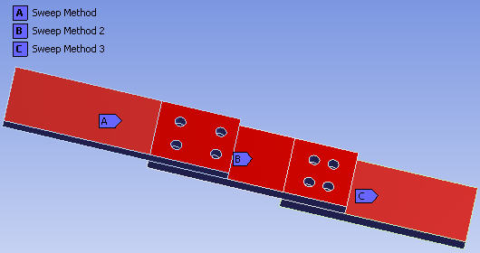
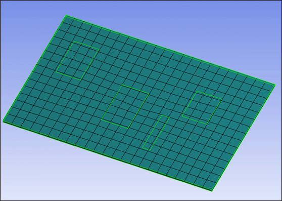
Figure 144: Three Plates Model Meshed with Thin Solid Sweeper shows the meshed model.