This method of meshing complements the free mesher. If a body's topology is recognized as sweepable, the body can be meshed very efficiently with hexahedral and wedge elements using this technique. The number of nodes and elements for a swept body is usually much smaller than ones meshed with the free mesher. In addition, the time to create these elements is much smaller.
Workbench will automatically check to see if the body fulfills the topological requirements for sweeping. It will then choose two faces that are topologically on the opposite sides of the body. These faces are called the source and target faces. Workbench will mesh the source face with quadrilateral and triangular elements and then copy that mesh onto the target face. It then generates either hexahedral or wedge elements connecting the two faces and following the exterior topology of the body.
Note:
This information applies to general sweeping. For requirements and usage information specific to thin model sweeping, see Thin Model Sweeping.
For descriptions of the sweep option settings, see Sweep Method Control.
Requirements for General Sweeping
A body cannot be swept if any of these conditions exist:
There is a completely contained internal void in the body.
If more than one source or target face exists on a body. (You must slice the body so that the sub-bodies produced may have one-to-one mapping of source and target bodies or use the MultiZone Method or Thin Sweep that support many-to-one configuration of source and target bodies.)
A source and target pair cannot be found. That is, the sweeper cannot find at least one path from a source surface to a target surface connected by edges or closed surfaces.
If a Sizing control is used on a body with hard edge sizing and the source and target faces contain hard divisions which are not the same for each respective edge.
When sweeping it is only necessary to apply hard divisions to one leg of the sweep path. If the path has multiple edges, you should apply your controls to that path.
If the sweep path is shared by another body and that path lies on the body's source or target face then more hard divisions may be needed to constrain the sweeper.
When using Virtual Topology with sweeping, avoid creating virtual cells that result in a fully closed surface. Fully closed surfaces cause difficulties for the swept mesher and may result in poor meshes. When selecting adjacent faces for inclusion in a virtual cell, it is best to use Virtual Topology to merge some (but not all) of the faces. A good approach is to use Virtual Topology for the smaller faces, but omit any larger faces from the virtual cell.
To preview any bodies that can be swept meshed, click Mesh on the Tree Outline and right-click the mouse. Select Show > Sweepable Bodies from the context menu to display bodies that fulfill the requirements of a sweepable body. However, even if these requirements are met, the shape of the body may at times still result in poorly shaped elements. In these cases, the tetrahedron mesher is used to mesh the body.
The Show Sweepable Bodies feature only displays bodies that can be swept in terms of topology where the source and target are not adjacent on an axis. It cannot automatically determine axis-sweepable bodies. However, these bodies can be meshed if a Sweep mesh method is applied and source and target faces are defined. A sweepable body may not be Sweep meshed if the body geometry is not suitable.
Show Mappable Faces is a good tool to diagnose side faces. All side faces should be mappable, but if they are not found to be mappable, it indicates there may be a problem with the topology. For help in diagnosing problems when using the Sweep method, refer to the description of the Edge group in the Mechanical help. This toolbar provides access to features that are intended to improve your ability to distinguish edge and mesh connectivity.
Other Characteristics of General Sweeping
Other characteristics of sweeping include the following:
The general sweeper ignores the Proximity Gap Factor setting, which is used to help define the proximity-based sizing.
Hard entities are not supported for the general sweeper.
If the sweep method is applied to a body and a mapped Face Meshing control is defined for either the body's source or target face, the sweep mesher will fail if a mapped mesh cannot be obtained for the face. See Notes on Face Meshing Controls for Mapped Meshing for related information.
The source and target faces do not have to be flat or parallel.
If the topology of the source and target face is the same, the sweeping operation will often succeed even if the shape of the source face is different from the shape of the target face. However, drastically different shapes can cause element shape failures.
Sweeping does not require your model to have a constant cross section. However, the best results are obtained for constant or linearly varying cross sections.
For swept meshes with inflation and match control, inflation is performed ahead of the match mesh and sweeping. This can affect the sizings on the match controls, which can in turn lead to meshing failure. Therefore, when using both match controls and inflation with sweeping, it might improve meshing robustness if you assign hard edge sizings to the high and low edges of the source face for the sweep.
Rules Followed By the General Sweeper
In deciding which area should be designated as the source area for general sweeping, the program uses the following rules, in the order as listed below. The sweeper will check all the rules until it finds a rule to use. Once a higher order rule is used, all the lower rules will not be considered. For example, if none of the first five rules apply, it will check against rule 6. In this case, if a face is a plane (flat) and the other face is not a plane (not flat), the flat face will be picked as the source and the test will be terminated.
Manually set control - specify both source and target: The source and target for sweeping will be exactly as you specify. This is the fastest way of meshing. It will eliminate searching for a possible source and target. For axis-sweeping, this method must be used. If a face is a source of another body and is not picked as a source of the current body, the aforementioned face will be used as a source.
Manually set control - specify source: Once the user specifies a source area, the program will try to find the target suitable to the source. The source will be exactly as specified.
Face Mesh control: The program finds the face with a mapped Face Mesh control applied to it.
Number of loops: The face with the largest number of loops will be picked as source face.
Number of lines: The face with the largest number of lines will be picked as source face.
Flat face: A flat face has higher priority for being a source face.
Less sharing: In most cases, a face might be used by one or a maximum of two bodies. If every one is flat (plane), the one used by the least number of bodies (that is, used by just one body) will be picked as source face.
Larger area: The largest area will be picked as the source.
Topological Requirements of the General Sweeper
The general sweeper must have at least one path between the source face and target face. The side faces of the sweep do not need to be singular but they must all be submappable and have single loops. The source face cannot be a closed analytic such as a full cylinder, torus or sphere. However, partial analytics are acceptable as source and target faces.
Note: Creo Parametric creates unique topological models that no other CAD system creates. In all other CAD systems, non-periodic faces can have only one exterior topological loop. On the other hand, models in Creo Parametric can have non-periodic faces with multiple exterior loops. This type of topology does not pose a problem for the free meshers in the Meshing application. However, it does pose a problem for the general sweeper. As noted above, side faces of the sweep must have single loops. They cannot have multiple exterior loops because if they do, a single path from the source to the target cannot be determined.
Importing the model into the DesignModeler application breaks the face with multiple exterior loops into multiple faces with single loops because the DesignModeler kernel does not support the Creo Parametric topology. Exporting the model from Creo Parametric to IGES or STEP format will also resolve this issue.
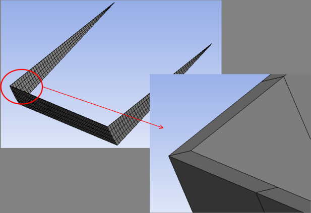
Using General Sweep to Mesh a Narrow Channel Body
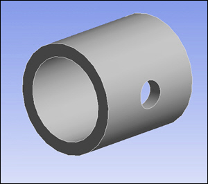
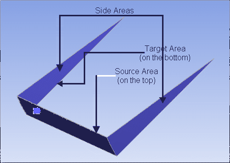
The series of images below illustrates the use of general sweep, along with mapped face meshing and hard edge sizing controls, to mesh a narrow channel body. Figure 123: Axial Sweep Model shows the source, target, and side areas of the axial sweep model used in this example.
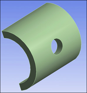
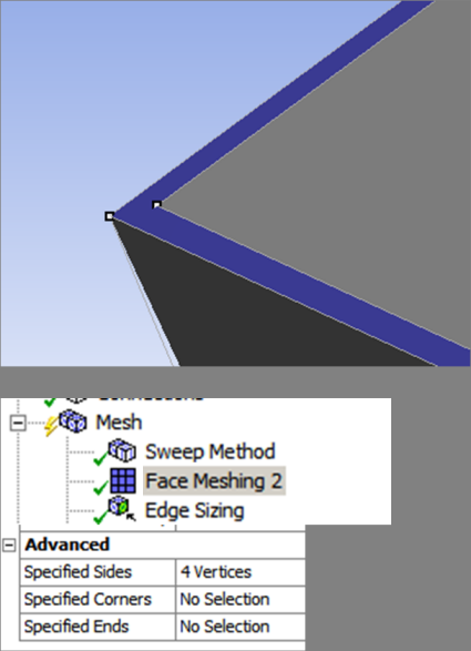
Because the source and target areas to be meshed are a narrow channel and you want them to be meshed with map mesh, it may present difficulties to the mesher. In Figure 124: Axial Sweep Model: Face Meshing Control, a mapped Face Meshing control is defined on the source face. Four vertices (two on each side area) have been selected for the Specified Sides control.
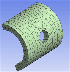
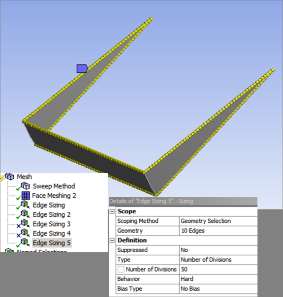
In cases similar to this example, the key to obtaining a successful mesh is the definition of a hard edge sizing control to make the two paired parallel edges. As shown in Figure 125: Axial Sweep Model: Hard Edge Sizing Control, set the Type to Number of Divisions and enter a value in the Number of Divisions field (in this case, 50). The Hard option ensures the number of divisions are the same on the pair of edges.
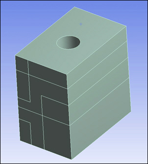
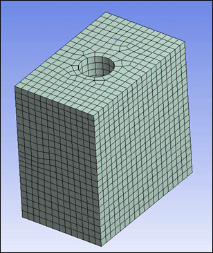
Finally, Figure 126: Axial Sweep Model: Meshed shows the mesh obtained using the settings described above.