


This section describes features that are common to all types of virtual topology.
Setting Advanced Properties
The following Advanced settings are available in the Details View for Automatic and Repair modes.
Generate on Update – Sets whether you want to include the settings in this Details View when you update the geometry.
Simplify Faces – Removes hard edges and hard vertices from the selection.
Yes: If the Simplify Faces property is turned on, the program removes hard edges and hard vertices.
No: If the Simplify Faces property is turned off, faces are not simplified.
Merge Face Edges – The property is relevant only during the virtual face creation process. It applies only to manually-created virtual faces and can be modified at any time, but the modification will have no effect on previously-created virtual faces.
Yes: If the Merge Face Edges property is turned on, the program will attempt to merge bounding edges of a newly manually-created virtual face and create virtual edges. The criterion used to merge edges is based on the Behavior setting.
No: If the Merge Face Edges property is turned off, only a virtual face will be created out of selected faces.
Lock position of dependent edge splits – See Locking Locations of Dependent Virtual Split Edges.
Virtual Faces, Virtual Edges, Virtual Split Edges, Virtual Split Faces, Virtual Hard Vertices, Total Virtual Entities – Read-only indications of corresponding counts in the model. See Viewing Virtual Topology Statistics.
Using the Virtual Topology Properties Dialog to Edit Properties
You can use the Virtual Topology Properties dialog to edit the properties of selected virtual topology entities.
To use a right mouse button click:
Highlight any object in the Tree Outline (for example, the Geometry or Mesh object).
In the Geometry window, select the virtual entities whose properties you want to edit.
Right-click and select Edit Selected Virtual Entity Properties....
Make the desired changes in the Virtual Topology Properties dialog.
To apply any changes and/or exit, press Enter on your keyboard or click X on the dialog.
To use the Virtual Topology context toolbar:
Highlight the Virtual Topology object in the Tree Outline.
In the Geometry window, select the virtual entities whose properties you want to edit.
Choose on the Virtual Topology context toolbar.
Make the desired changes in the Virtual Topology Properties dialog.
To apply any changes and/or exit, press Enter on your keyboard or click X on the dialog.
Remember the following information when using the Virtual Topology Properties dialog:
If all selected virtual entities have the same value for a particular property, that value appears in the Virtual Topology Properties dialog. Otherwise, the value for that property is blank.
Fields that are grayed out are read-only.
The changes you make in the Virtual Topology Properties dialog will be applied to all selected virtual entities.
If you change a split location, the graphic in the Geometry window will be redrawn.
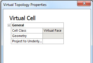
Consider the examples below. For the first example, two virtual faces were selected. One virtual face was composed of five faces, and its Project to Underlying Geometry option was set to No. The other virtual face was composed of three faces, and its Project to Underlying Geometry option was set to Yes.
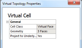
In the example below, two virtual faces were selected. In this case each virtual face was composed of three faces, and Project to Underlying Geometry was set to Yes for both virtual faces.
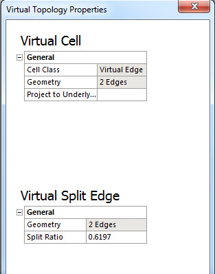
In the example below, two virtual edges and one virtual split edge were selected. Both virtual edges were composed of two edges, but Project to Underlying Geometry was set to Yes for one virtual edge and to No for the other.
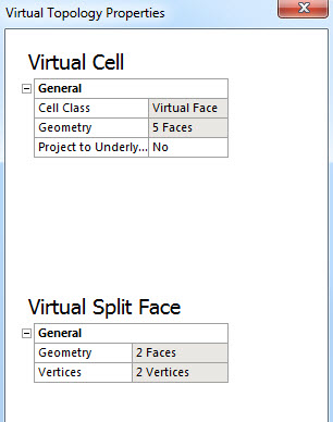
In the example below, one virtual face and one virtual split face were selected. The virtual face was composed of five faces, and its Project to Underlying Geometry option was set to No.
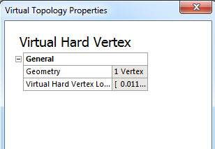
In the example below, one virtual hard vertex was selected.
Note: Although you cannot use the dialog to modify the Virtual Hard Vertex Location, you can do so interactively using the F4 key. See Creating and Managing Virtual Split Faces for details.
Viewing Virtual Topology Statistics
The Details View of the Virtual Topology object provides counts of the following:
Virtual faces
Virtual edges
Virtual split edges
Virtual split faces
Virtual hard vertices
Total virtual entities
Remember the following information when viewing virtual topology statistics:
Statistics are updated whenever a geometry or virtual topology change occurs.
If any body is suppressed, the virtual topology entities on that body are not counted.
If you create a virtual topology entity and then use it to create another virtual topology entity, the former exists in the background in a suppressed state and is not counted.