


You can specify as your Scoping Method for a Named Selection.
Doing so displays the Worksheet window. By default, this window displays below the Geometry pane in Mechanical. Worksheet data entries define the criteria for Named Selections based on geometric or meshing entities. Each row of the worksheet performs a calculation for the specified criteria. If multiple rows are defined, the calculations are evaluated and completed in descending order.
Named Selections Defined by Worksheet Criteria
Highlight the Selection object. In the Details view, set Scoping Method to Worksheet.
As needed, right-click the mouse and select .
Enter data in the worksheet for specifying the criteria that will define a Named Selection. See the Worksheet Entries and Operation section below for specific entry information.
Click the button located on the Worksheet to create the Named Selection based on the specified criteria. Alternatively, you can right-click the Named Selection object and choose Generate Named Selection from the context menu.
Note:
If you change the Scoping Method from Geometry Selection to Worksheet, the original geometry scoping will remain until you select Generate.
When you select Generate and the generation fails to produce a valid selection, any prior scoping is removed from the Named Selection.
If there is no indication that the worksheet has been changed and the Named Selection should be regenerated, you still may want to select Generate to ensure that the item is valid.
If a row inside the worksheet has no effect on the selection, there are no indications related to this.
Named Selections require valid scoping. If the application detects a criterion that is not properly scoped, it becomes highlighted in yellow to alert users of a possible problem. A highlighted criterion does not effect on the overall state of the object.
Named Selections created using the Worksheet may not support virtual entities.
Worksheet Entries and Operation
A sample worksheet is illustrated below. Criteria of the Worksheet is defined by making selections in the drop-down menus of the columns for each row. Certain values are read-only or they are only available as the result of other criterion being specified.
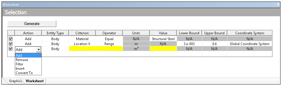
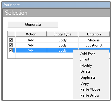
As illustrated here, when you add a row into the Worksheet, right-click context menu options become available. When using these options, you need to also click the button to have these changes applied to the Named Selection.
The content of each Worksheet column is described below.
Action column:
: Adds the information defined in the current row to information in the previous row, provided the item defined in the Entity Type column is the same for both rows.
: Removes the information defined in the current row from information in the previous row, provided the geometry defined in the Entity Type column is the same for both rows.
: Establishes a subset of the information defined in the previous row.
: Selects all items of the same Entity Type that are not currently in the named selection.
: Changes the geometric Entity Type selected in the previous row. The change is in either direction with respect to the topology (for example, vertices can be converted "up" to edges, or bodies can be converted "down" to faces). When going up in dimensionality, the higher level topology is selected if you select any of the lower level topology (for example, a face will be selected if any of its edges are selected).
Mesh Nodes: You can convert a geometry selection (bodies, edges, faces, vertices) to mesh nodes. The nodes that exist on the geometry (that is, the nodes on a face/edge/vertex or nodes on and within a body) will be selected. In addition, node-based Named Selections can be converted to elements and element-based Named Selections can be converted to nodes using this action. Element Faces: You can convert a face-based Named Selection, a node-based Named Selection, or a body-based Named Selection to an Element Face Named Selection. Face- and node-based conversion does not support element faces that share two (or more) bodies. However, for body-based conversion, you can specify the Criterion options or to specify whether to include shared element faces.
The Entity Type column:
: This option does not support element faces defined on shell bodies.
Criterion column:
- available when Entity Type = , , or .
- available when Entity Type = , , , or , or .
Important: For criterion, the calculation of the centroid is not supported for Line Bodies.
: available when Entity Type = , , or , and the Value column is a Body with the Treatment property set to .
- available when Entity Type = .
- available when Entity Type = or . Applies to faces that are cylindrical and edges that are circular.
Distance
Important: Line Bodies are not supported for the Distance Criterion option.
- available when Entity Type = . The option requires you to specify an axis entry, either positive or negative X, Y, or Z in the Value column. Based on that selection, the application creates a Named Selection that includes all element faces whose normal direction is same as the selected axis (for the selected Coordinate System, global or user-defined).
When using the selection for the Criterion and you have defined a cylindrical coordinate system:
The (positive) option selects element faces that have their normal pointing radially outward in the specified cylindrical coordinate system.
The (negative) option selects element faces that have their normal pointing radially inward in the selected cylindrical coordinate system.
The application does not support the options for cylindrical coordinate systems.
- available when Entity Type = , , . This option is useful when you want to create a Named Selection of faces, edges, or vertices shared across bodies.
- available when Entity Type = . This option is useful for examining and working with shared nodes that were generated by Node Merge or Mesh Connection operations.
- available when Action = and Entity Type = . This option requires a Value entry. The Value entry defines the number of elements to which a node is connected. For example, if you enter a Value of , the application selects every node in the model that is connected to four elements.
This option supports 2D and 3D analyses for all element types.
- available when Entity Type = .
- available when Entity Type = .
- available when Entity Type = . This option is supported for surface/shell bodies only.
- available when Entity Type = .
when Entity Type = .
- available when Entity Type is .
- available when:
Action =
Entity Type = or (node-based conversion only)
- available when:
Action =
Entity Type = or (node-based conversion only)
For Entity Type = .
You may wish to refer to the Mesh Metric section of the Meshing User's Guide for more information about these Criterion options.
Operator column:
- available when Criterion = or .
includes Lower Bound and Upper Bound numerical values that you enter.
- only available when Action column =
- only available when Action column =
Note: The and options apply to the entire model. They do not function with any other worksheet criteria entry. Therefore, they are only available when the Action column is set to .
Units column: read-only display of the current units for Criterion = or .
Value column:
For Criterion = , enter positive numerical value.
For Criterion = or , enter numerical value.
Note: Selection location is at the centroids of edges, faces, bodies, and elements.
For Entity Type = and Criterion = :
For Entity Type = and Criterion = : select the desired cross section name from the drop-down list.
For Entity Type = and Criterion = :
For Entity Type = Criterion = :
For Entity Type = and Criterion = :
For Entity Type = and Criterion = , enter a valid body name. When:
Operator = , you can enter a partial body name. The application matches name characters at the beginning, middle, or at the end of the name.
Operator = , you must enter the body name exactly as it appears in the Geometry folder.
Operator = , you enter the body name that you do not wish to include in your named selection. The application will select all other bodies from the Geometry folder.
For Entity Type = and Criterion = :
For Entity Type = and Criterion = : the Value field options include // and //. This axis selection is based on the coordinate system defined in the Coordinate System column.
For Entity Type = and Criterion = , enter the number of shared edge connections. For example, enter Value = 0 for edges not shared by any faces, enter Value = 1 for edges shared by one face, and so on.
For Criterion = , you can include a previously defined named selection from the Value field.
For Criterion = and Operator = , you can specify the name of multiple Named Selections, or, as desired, only a portion of the name of multiple Named Selections in the Value field. For example, for NS1, NS2, and NS3, you can create a new Named Selection that includes all three by specifying “NS” in the Value field.
Note: Whenever you create a Named Selection that references an existing Named Selection using the Criterion option, it is recommended that you use the Generate Named Selections context (right-click) menu option from the Named Selections folder to generate your Named Selections. This action calculates the relationship between all the Named Selections contained in the folder to determine the correct order for generation. Using the Worksheet Generate option updates only the selected/active Named Selection. Therefore, if that Named Selection has a reference to another Named Selection, the associated Named Selection is not regenerated.
Furthermore, the Generate Named Selections option makes sure that the application updates all child objects of the Named Selection folder in the appropriate order while making sure that the application does not create any cyclic dependencies (also called a closed loop reference) between Named Selections. A cyclic dependency occurs when you have one or more named selections that depend upon one another to generate results. If this is detected, the application generates an error.
For Criterion = , you can include a previously-defined named selection in the Value field. You can select from the named selections provided in the list only.
For Criterion = , select the desired material from the drop-down list. See the Material Assignment topic for more information.
For Criterion = Distance, enter a positive numerical value. The distance is the difference between the origin of the selected coordinate system and the centroid of the scoped geometry (body, face, edge).
Important: Line Bodies are not supported for the Distance Criterion option.
For Criterion = , enter a positive numerical value or values based on the selection made in the Operator column.
Lower Bound column: enter numerical value.
Upper Bound column: enter numerical value.
Coordinate System column:
Global Coordinate System
Any defined local coordinate systems
Adjusting Tolerance Settings for Named Selections by Worksheet Criteria
Tolerance settings are used when the Operator criterion is defined as an "equal" comparison. Tolerances are not used when doing greater than or less than operations. Tolerance values apply to the entire worksheet. If you wish to adjust the tolerance settings for worksheet criteria, use the Tolerance settings in the chosen Named Selection’s Details view.
By default, the Zero Tolerance property is set to 1.e-008, the Relative Tolerance value is set to 1.e-003, and the Angular Tolerance is set to 1°. As a result of the significant digit display, the value used for calculations and the display value may appear to be different. The Zero Tolerance property’s value is past the number of significant digits that Mechanical shows by default. The application’s default setting for significant digits is 5 (the range is 3 to 10). This setting affects only the numbers that are displayed, any calculation or comparison uses the actual values when processing. In addition, it is important to note that most values (including selection values seen in the status bar and the Selection Information window) in Mechanical display in a significant digit format. See the Appearance option in the Setting Ansys Workbench section of the Help for information about changing default display settings.
Setting the tolerance values manually can also be useful in meshing, when small variances are present in node locations and the default relative tolerance of .001 (.1%) can be either too small (not enough nodes selected) or too big (too many nodes selected).
In the Details view, set Tolerance Type to .
Specify the properties as desired: Zero Tolerance, Relative Tolerance, and Angular Tolerance. The Zero Tolerance and Relative Tolerance values are dimensionless. Relative Tolerance is a multiplying factor applied to the specified worksheet value. For example, if you want a tolerance of 1%, enter .01 in the Relative Tolerance field. Angular Tolerance is specified in degrees or radians. The Angular Tolerance setting determines when the normal direction of an element face is equal to the direction of your specified coordinate system.
Note: Angular tolerance is available for Worksheet-based Named Selections only. It is applicable once you set the Criterion to and the Entity Type to .
All comparisons are done in the CAD unit system. If your current unit system is not the same as the CAD unit system, the values entered will first be converted to the CAD unit system before searching for criteria.