


Using selective meshing, you can selectively pick bodies and mesh them incrementally. After meshing a body, you can mesh the entire part or assembly or continue meshing individual bodies. To generate the rest of the mesh in the model, use the Generate Mesh feature.
The following mesh methods are supported:
For solid meshing:
For surface meshing:
Remember the following information when using selective meshing:
Selective meshing is enabled by default. You can use the Allow Selective Meshing option to disable it. See Disabling Selective Meshing for information about Meshing application behaviors when selective meshing is disabled.
Selective meshing is not persistent for a geometry update or re-mesh operation. However, you can use the Mesh worksheet to create a selective meshing history so that your meshing steps can be repeated in the desired sequence. Otherwise, you must manually re-mesh bodies in the desired sequence. Refer to Using the Mesh Worksheet to Create a Selective Meshing History for details.
When using the Preview Surface Mesh, Preview Source and Target Mesh, or Preview Inflation feature during selective meshing, the previewed mesh will be discarded when you perform a subsequent preview or full mesh operation. The previewed mesh will not be used to seed the subsequent mesh operation.
After meshing, the meshed status icon appears in the Tree Outline for a meshed body within the Geometry folder, or for a multibody part whose child bodies are all meshed. If you make changes after meshing that invalidate the mesh for an individual body (such as adding sizing to the body), you will need to re-mesh that body only.
In a multibody part, if any child bodies have been meshed and refined, another child body is unmeshed, and you subsequently mesh the unmeshed body, the mesh state of all refined bodies in the part will be invalidated and re-meshed during mesh generation. Similarly, if one body is unmeshed and refinement is needed on another, generating the mesh will result in meshing and refinement of the entire part. In addition to cases involving refinement, this behavior applies in cases where post inflation is used.
When meshing a body that is part of a symmetry object, match control, or pinch control, all bodies to which the control is applied need to be meshed at the same time. Also, if a body that is part of a symmetry object, mesh connection object, contact match object, match control, or pinch control fails to mesh, the body will have an invalid mesh state that will propagate to all other bodies that are part of the respective object/control.
Mesh connections, contact matches, post inflation, and refinement are not performed until all body meshes have been generated. These operations will either be performed when the last body is meshed through selective meshing, or in the last step of the Generate Mesh operation.
Selective meshing is boundary constrained. That is, if you add a size control to a face that is adjacent to an up-to-date body, the edges of that face will be recovered from the existing mesh. Due to the boundary constraints, the mesher cannot split the edges to aid in meshing and will fail if it attempts to do so.
When you mix mesh methods in multibody parts, the manner in which topology shared by multiple bodies is protected depends on whether adjacent bodies are being meshed with Patch Independent methods (Patch Independent Tetrahedron, MultiZone, or MultiZone Quad/Tri) and/or Patch Conforming methods (Patch Conforming Tetrahedron, Sweep [general or thin], or Hex Dominant):
The interface between a Patch Conforming method and a Patch Conforming method is not protected.
The interface between a Patch Conforming method and a Patch Independent method is completely protected.
Only the boundary is protected at the interface between a Patch Independent method and a Patch Independent method.
You can use the Verbose Messages from Meshing option to control the verbosity of messages returned to you. Depending on the setting, before meshing a message reports the subset of bodies that is going to be meshed and/or after meshing a message reports the subset of bodies that failed to mesh.
Size controls on neighboring bodies are not considered, if you are performing selective meshing. This limitation is applicable to all mesh methods that support selective meshing. However, its impact may differ depending on the methods being used.
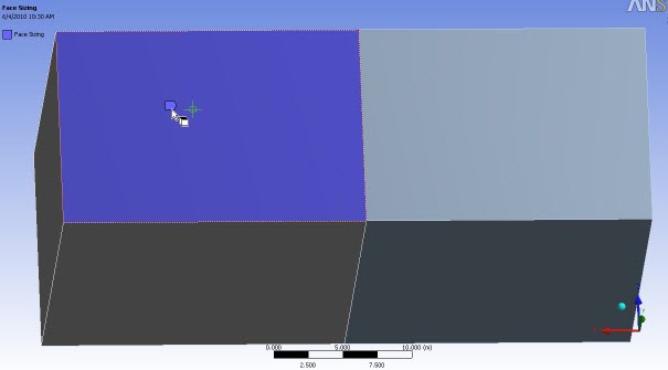
For example, consider the simple model below, which consists of two boxes to which the Patch Independent Tetra mesh method has been applied. A local size control that defines a much smaller Element Size than the global size has been scoped to the top face of the box on the left.
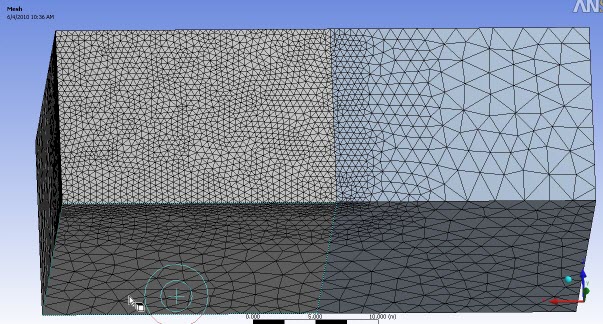
When the mesh is generated in one step (for the entire part rather than body by body), there is a smooth transition from the fine element size to the coarse element size, as shown in Figure 179: Mesh Generated for Entire Part.
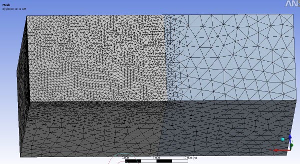
However, the mesh will differ if selective (body by body) meshing is performed. Figure 180: Selective Meshing: Left Body First shows the mesh when the body on the left is meshed first, and the body on the right is meshed second. In this case although the results are different than those in the figure above, the mesh may still be acceptable because the impact of the local size control on the left body has influenced the boundary mesh of the right body.
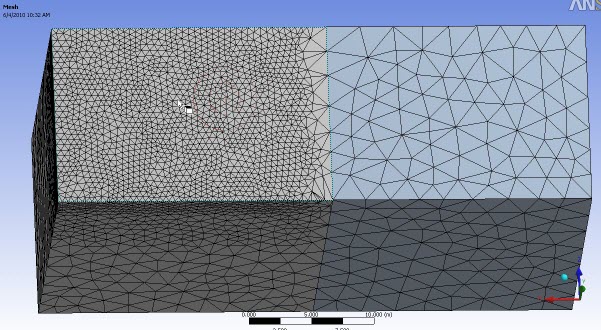
In Figure 181: Selective Meshing: Right Body First, the body on the right was meshed first, and the body on the left was meshed second. When this meshing sequence is used, the mesh on the right body does not recognize the size control that is scoped to the body on the left. This results in a coarse mesh on the right body with the transition region occurring on the left body.
When Mesh Based Connection is set to Yes,Selective Meshing is not supported.
Disabling Selective Meshing
Set the Allow Selective Meshing option to No to disable selective meshing. The Meshing application behaves as follows when selective meshing is disabled:
If you make changes after meshing that invalidate the mesh for an individual body in a multibody part (such as adding sizing to the body), the mesh for all bodies in the part is invalidated and you will need to re-mesh all bodies.
If one body in a multibody part is suppressed and you mesh all the other bodies, unsuppressing the suppressed body invalidates the mesh for all the bodies within that part. When you regenerate the mesh, all the bodies within that part will be re-meshed. If the model contains multiple parts, bodies in the other parts will not be affected and will not be re-meshed.
The Generate Mesh, Preview Surface Mesh, and Clear Generated Data RMB menu options are unavailable for individual bodies in multibody parts in the Tree Outline. To use these features for a multibody part, you must right-click at the part level in the Tree Outline.
There is no flyout menu for the Generate Mesh, Preview Surface Mesh, and Clear Generated Data RMB menu options in the Geometry window. If you select one of these options, the action is performed on the entire part.
Note: In some cases, the mesh may be generated in a selective fashion (body by body) even if selective meshing is currently disabled. For example, if you use selective meshing to mesh some of the bodies in a part, then disable selective meshing, and then generate the mesh and the mesh process does not invalidate any bodies, the mesh is generated using selective meshing processes. To avoid this behavior, you can use the Clear Generated Data feature or force a change of the mesh state on the part. Non-selective meshing will be used for all subsequent meshing.
Using the Mesh Worksheet to Create a Selective Meshing History
When you perform selective meshing, you control the sequence in which bodies are meshed. You can use the Mesh worksheet to create a selective meshing history, so that your meshing steps can be repeated in the desired sequence for any geometry update or re-mesh operation. Figure 182: Mesh Worksheet shows a sample Mesh worksheet. Each row in the worksheet corresponds to a step in the meshing sequence. When you generate the mesh, the software processes the steps one by one. For each step, the software selects the bodies identified by the specified Named Selection and meshes those bodies using the meshing controls that are applied to them.
Note: The Mesh worksheet is a helpful meshing tool, but it does not manage mesh state. State management is handled at the prototype (Body object) and mesh levels. Mesh state is visible in the Tree Outline in the Geometry folder and in the Mesh folder. See Understanding States for more information.
There are two ways to create a selective meshing history:
By recording meshing steps as you perform them
By adding meshing steps to the worksheet manually
To create a selective meshing history by recording your steps:
Click the Mesh object in the Tree Outline.
Do one of the following:
Right-click the Mesh object and select Start Recording from the context menu. As a result, the worksheet opens in recording mode automatically. -or- Click the Worksheet button on the toolbar and click the Start Recording button on the worksheet. Move the worksheet to the desired location to dock it. The location will persist whenever the Mesh object or one of its child objects is highlighted in the Tree Outline. For example, you may want to dock the worksheet alongside the Geometry window, allowing you to view both at once.
Note: The worksheet is not dockable on Linux platforms. On Linux, you can drag the worksheet off the Meshing application interface, and it will then appear in its own separate window.
Do one of the following:
Select one or more bodies or parts in the Geometry window, right-click, and select Generate Mesh on Selected Bodies. If you did not dock the worksheet, you may need to click the Worksheet button on the toolbar or the Graphics tab at the bottom of the worksheet to return to the Geometry window first. -or- Select one or more bodies or parts in the Tree Outline, right-click, and select Generate Mesh. As a result, a Named Selection for the selected set is generated (named Meshing_1, Meshing_2, Meshing_3, and so on) and is added to the worksheet automatically.
During recording, other steps in the worksheet are ignored while the mesh for the selected set is being generated. See below for additional notes on recording and playback behaviors.
Repeat step 4 for each meshing step in the desired sequence.
When you are done meshing bodies/parts, do one of the following:
Right-click the Mesh object and select Stop Recording from the context menu. -or- Click the Stop Recording button on the worksheet. Note: You do not have to record the meshing for all bodies, only those for which you want to record the meshing order. See Mesh Worksheet Recording and Playback Behaviors for details.
To create a selective meshing history manually:
Click the Mesh object in the Tree Outline.
Click the Worksheet button on the toolbar.
Move the worksheet to the desired location to dock it. The location will persist whenever the Mesh object or one of its child objects is highlighted in the Tree Outline. For example, you may want to dock the worksheet alongside the Geometry window, allowing you to view both at once.
Note: The worksheet is not dockable on Linux platforms. On Linux, you can drag the worksheet off the Meshing application interface, and it will then appear in its own separate window.
Add a row to the worksheet by right-clicking on the table and selecting Add from the context menu.
In the new row, click the Named Selection column and select a Named Selection from the Named Selection drop-down.
Repeat steps 4 and 5 for each meshing step in the desired sequence.
Mesh Worksheet Recording and Playback Behaviors
Remember the following information regarding recording and playback behaviors:
During recording, the button in the upper-right corner of the worksheet is red. When recording is stopped, the button is green.
When you start recording, the software checks for meshed bodies and verifies that each meshed body is accounted for in the worksheet. If any extraneous meshed bodies are found, recording does not occur and an error message is issued. You must clear the mesh entirely (or at least clear the mesh from the bodies that are not being used by the worksheet) before you can begin recording. To do so, use the Clear Generated Data option or click the Clear Generated Mesh button on the worksheet.
When you start recording, the states of the bodies being used by the worksheet are checked. If any body is not in a meshed state, recording does not occur and an error message is issued. You must bring the mesh up-to-date before you can begin recording. To do so, right-click the last step in the worksheet and select Generate Mesh Through This Step from the context menu. See below for more information about using this option.
As steps are being recorded, they are appended to the existing steps in the worksheet.
Other steps in the worksheet are ignored while the mesh for the selected set is being generated.
After you have entered recording mode, recording stops when the mesh is up-to-date. An exception to this behavior occurs if you record one or more steps but then suppress all remaining unmeshed bodies. In such cases, the mesh will be up-to-date but recording will not stop automatically. You must click Stop Recording.
During recording/playback, post mesh operations (including mesh connections, contact matches, post inflation, and refinement) do not occur until the last step in the worksheet, after all meshing is complete.
If you select the Preview Surface Mesh, Preview Source and Target Mesh, or Preview Inflation feature, recording stops and a warning message is issued.
The Generate Mesh option is context sensitive. It behaves differently depending on where you invoke it. If you invoke it from the Mesh object in the Tree Outline (RMB on Mesh folder > Generate Mesh), it behaves similar to the Preview options in that recording stops. If you invoke it from the Geometry object (RMB on Geometry folder > Generate Mesh) or from the Geometry window (RMB > Generate Mesh On Selected Bodies), the operation is treated as a selective meshing step and is recorded.
If you insert a step manually, recording stops and a warning message is issued.
If you delete a step manually, recording stops and a warning message is issued.
If the mesh fails, recording stops and a warning message is issued.
To replay steps incrementally, right-click in the row of interest and select Generate Mesh Through This Step from the context menu. As a result, recording stops, any existing mesh is cleared, and all meshing steps prior to and including the selected step are replayed in the Geometry window.
Mesh Worksheet Named Selection Behaviors
Remember the following information regarding Named Selection behaviors:
Only Named Selections that consist of bodies are selectable from the worksheet's Named Selection drop-down.
If the model contains bodies that are not included in any Named Selection, these bodies are meshed last.
If a Named Selection is used by the worksheet, the Used by Mesh Worksheet field in the Details View for that Named Selection is set to Yes, even if the corresponding worksheet step is inactive.
For Named Selections that are generated automatically by the worksheet, the Send to Solver option in the Details View is set to No by default. The default is Yes for Named Selections that you create. The worksheet respects the user-defined settings. That is, if you create a Named Selection, retain the Send to Solver setting of Yes, and subsequently use that Named Selection in the worksheet, the Named Selection will be passed to the solver as expected.
If a change to a Named Selection being used by the worksheet causes the Named Selection to become underdefined or invalid, the corresponding worksheet step will be deactivated without invalidating the worksheet. Reasons a Named Selection may become underdefined or invalid include:
You change the scope of a Named Selection from body to face/edge
A geometry update changes the scope of a Named Selection, or causes the software to try to delete the Named Selection
If you delete a named selection manually, recording stops and a warning message is issued.
From the Tree Outline, you can suppress/unsuppress Named Selections or bodies included in Named Selections that are being used by the worksheet, and the corresponding worksheet step will be deactivated/activated accordingly without invalidating the worksheet.
You also can activate/deactivate steps directly on the worksheet. By default, a check mark (
 ) appears on the worksheet, meaning steps
that correspond to all unsuppressed bodies/Named Selections are active. To deactivate a single
step, clear the corresponding check box. To deactivate all active steps, click and it is replaced by
) appears on the worksheet, meaning steps
that correspond to all unsuppressed bodies/Named Selections are active. To deactivate a single
step, clear the corresponding check box. To deactivate all active steps, click and it is replaced by  . Toggling between and activates/deactivates the steps corresponding to all unsuppressed bodies/Named Selections.
Toggling step activation on the worksheet has no effect on the suppressed status of the
corresponding bodies/Named Selections in the Tree Outline.
. Toggling between and activates/deactivates the steps corresponding to all unsuppressed bodies/Named Selections.
Toggling step activation on the worksheet has no effect on the suppressed status of the
corresponding bodies/Named Selections in the Tree Outline.When a step is inactive, its row in the worksheet is grayed out. Inactive steps are skipped during mesh generation and other worksheet operations.
To obtain the example shown in Figure 183: Mesh Worksheet Step Deactivation, the Converter Named Selection was suppressed in the Tree Outline.
Miscellaneous Points to Remember
To delete a row from the worksheet, right-click in the row of interest and select Delete from the context menu. The worksheet, including the meshing sequence, will be updated automatically.
Click the Delete All Steps button to clear all data from the worksheet.
If the mesh fails at any point in the process, the process terminates but returns as much of the mesh as possible.
If you change the worksheet after you mesh, those changes will not be reflected in your meshing state as the worksheet does not affect meshing state. The changes will take effect the next time you generate a mesh.
If you select bodies to mesh individually (by using the Generate Mesh On Selected Bodies option in the Geometry window, the Generate Mesh option in the Geometry folder, or by using the Preview Surface Mesh, Preview Source and Target Mesh, or Preview Inflation feature), the Meshing application ignores the worksheet and generates the mesh for the selected bodies.
If you select Part or Body objects in the Geometry folder in the Tree Outline, right-click, and then select Generate Mesh from the context menu, the Meshing application ignores the worksheet and generates the mesh for the selected parts/bodies.
When you resume a saved project from an older release, you should generate worksheet based named selections manually after meshing to update the named selections.
When generating a mesh from the Mesh Worksheet, if the last step fails, mesher attempts to remesh the entire part, including bodies not listed in the named selection.